2 layers99.7 × 63.9 mm
NES CN ROM-256-05
emeargt/nes-cnrom
KiCad project for NES-CN-ROM-256-05 cartridge schematic and PCB
17 parts31CC-BY-SA-4.0

 sailor-elite/on_off_switch_ASG
ATtiny13a PCB off Switch design and program for AS&G System in Mistubishi ASX and Citroen C4 Aircross.
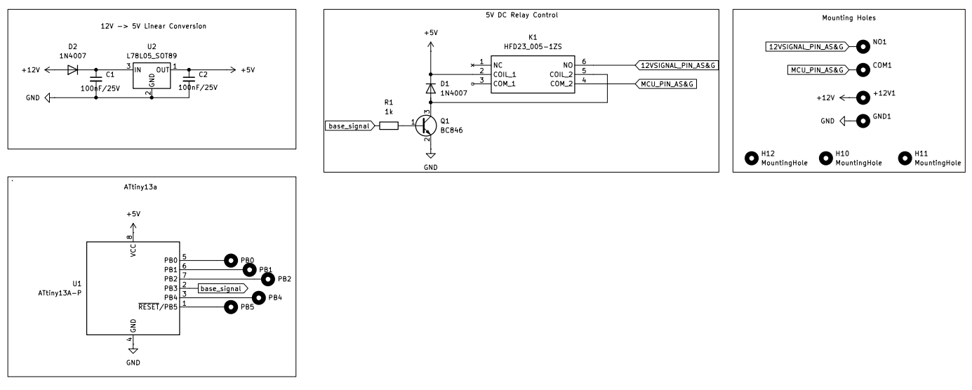
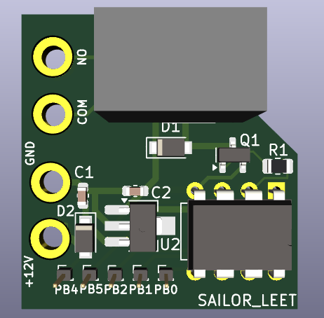
On off switch is an open-source printed circuit board by sailor-elite, from the sailor-elite/on_off_switch_ASG repository on GitHub. It is a 2-layer board of 25.9 × 27.8 mm with 18 parts on 16 nets, routed with 67 tracks and 0 vias.
It is built around the ATTINY13A-PU and BC846. Its parts include 2 capacitors, 2 ICs, 2 diodes, 1 resistor and 1 transistor. It belongs with the AVR (ATmega, ATtiny) boards of this library.


This project implements an automatic Stop and Go Off Switch for the AS&G (Auto Stop & Go) system in Mitsubishi ASX and Citroën C4 Aircross. The switch is designed to enhance user convenience by automatically disabling the AS&G system after ignition.
| Reference | Value | Footprint |
|---|---|---|
| C1, C2 | 100nF/25V | Capacitor_SMD:C_0603_1608Metric |
| D1, D2 | 1N4007 | Diode_SMD:Nexperia_CFP3_SOD-123W |
| K1 | HFD23_005-1ZS | relays:HFD230051ZS |
| Q1 | BC846 | Package_TO_SOT_SMD:SOT-23 |
| R1 | 1k | Resistor_SMD:R_0805_2012Metric |
| U1 | ATtiny13A-P | Package_DIP:DIP-8_W7.62mm |
| U2 | L78L05_SOT89 | Package_TO_SOT_SMD:SOT-89-3_Handsoldering |
To compile and upload the code for the ATtiny13A, the following tools and libraries are required:
| Qty | Value | Footprint | References |
|---|---|---|---|
| 5 | MountingHole_Pad_MP | Connector_PinHeader_1.00mm:PinHeader_1x01_P1.00mm_Vertical | PB0, PB1, PB2, PB4, PB5 |
| 4 | MountingHole_Pad_MP | MountingHole:MountingHole_2.2mm_M2_DIN965_Pad | +12V, COM, GND, NO |
| 2 | 100nF/25V | Capacitor_SMD:C_0603_1608Metric | C1, C2 |
| 2 | 1N4007 | Diode_SMD:Nexperia_CFP3_SOD-123W | D1, D2 |
| 1 | 1k | Resistor_SMD:R_0805_2012Metric | R1 |
| 1 | ATtiny13A-P | Package_DIP:DIP-8_W7.62mm | U1 |
| 1 | BC846 | Package_TO_SOT_SMD:SOT-23 | Q1 |
| 1 | HFD23_005-1ZS | relays:HFD230051ZS | K1 |
| 1 | L78L05_SOT89 | Package_TO_SOT_SMD:SOT-89-3_Handsoldering | U2 |
emeargt/nes-cnrom
KiCad project for NES-CN-ROM-256-05 cartridge schematic and PCB

digilogistist/The-Open-Source-USB-NES-Project
USB-NES and NES-FASTGFX product engineering repository


WiiMake/picones
In the last 40 years, technology has advanced to the point were what used to be done in hardware can now be done in software. This project uses an rp2350 to emulate a ROM chip on an NES Cartridge.


bazsimarkus/a277d-led-tachometer
An analog LED tachometer controlled by an East German A277D chip (clone of UAA180), featuring an integrated ATtiny13A-based digital ignition pulse generator for testing.
It measures 25.9 × 27.8 mm and has 2 copper layers, 1.6 mm thick.
18 parts, built around the ATTINY13A-PU and BC846. The full list of its parts is on this page, with links to each part's symbol and footprint where PCBKit's library has them.
From the sailor-elite/on_off_switch_ASG repository on GitHub, at the commit this page was made from: the board is on_off_switch/on_off_switch.kicad_pcb and its schematic on_off_switch/on_off_switch.kicad_sch. PCBKit opens the board in the browser, with nothing to install.
Its repository states no licence, so its author keeps all rights: ask sailor-elite before reusing the design.