
2 layers152.4 × 101.6 mm
8088-FE2010A SBC
skiselev/micro_8088
Micro 8088 - IBM XT Compatible Processor Board based on Faraday FE2010 chipset
72 parts412GPL-3.0

 rylansturm/GaragePi
Another retro-fitted smart garage door controller using a Raspberry Pi.
GaragePi PCB is an open-source printed circuit board by rylansturm, from the rylansturm/GaragePi repository on GitHub, published under the GPL-2.0 licence. It is a 2-layer board of 65 × 56 mm with 17 parts on 41 nets, routed with 98 tracks and 10 vias.
It is built around the PN2222A. Its parts include 5 connectors, 2 resistors, 2 diodes, 2 transistors and 2 switches.
About a month ago I got the case printed and everything mounted in my garage. The sensors are IR prox sensors that sit just above the door when closed, but the PCB can work with anything that has a 3.3V, GND, and Sensor pin configuration. The wiring is a CAT5 cable terminated with an aviation plug on the Pi side and screw terminals on the sensor side.
I can access the Pi remotely via SSH. I am now working on setting up an MQTT (Mosquitto) broker on my home network. Then I'll work on setting up an API and GUI on my public server so remote access is more user friendly.
Non-destructive. The project must not remove anything from the current garage door system. Wires can be added into and below the physical buttons that are on the garage wall now. Disconnection should be easy.
Open/Close. A relay can be used to make the connection that send the signal to the garage openers.
Scalable. The system should support my two garage doors, and should ideally be scalable up or down easily. One door without useless clutter in the UI, 3 doors just as simply.
Sensors. I should be able to read the current state of the garage.
A minimum viable project is one where I can control my garage door via ssh when connected to WiFi. That just means Raspberry Pi, Relay board, and a local bash script. Let's go.
Minimum viable project is in place. I can now open and close garage doors by running the rust script with argument '1' or '2'. Only from local network. No monitoring system in place
A PCB has been designed that will sit on top of the Pi. It has been ordered and should be in place in the next week or so. Now on to designing the sensors.
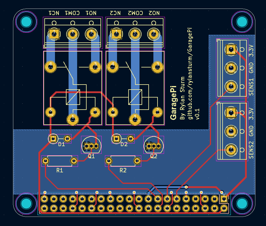
| Qty | Value | Footprint | References |
|---|---|---|---|
| 4 | MountingHole | MountingHole:MountingHole_2.7mm_M2.5 | H1, H2, H3, H4 |
| 4 | Screw_Terminal_01x03 | TerminalBlock_RND:TerminalBlock_RND_205-00013_1x03_P5.00mm_Horizontal | J1, J2, J4, J5 |
| 2 | D | Diode_THT:D_DO-35_SOD27_P3.81mm_Vertical_AnodeUp | D1, D2 |
| 2 | PN2222A | Package_TO_SOT_THT:TO-92_Inline | Q1, Q2 |
| 2 | R | Resistor_THT:R_Axial_DIN0207_L6.3mm_D2.5mm_P7.62mm_Horizontal | R1, R2 |
| 2 | SANYOU_SRD_Form_C | Relay_THT:Relay_SPDT_SANYOU_SRD_Series_Form_C | K1, K2 |
| 1 | Raspberry_Pi_2_3 | Connector_PinSocket_2.54mm:PinSocket_2x20_P2.54mm_Vertical | J3 |
It measures 65 × 56 mm and has 2 copper layers, 1.6 mm thick.
17 parts, built around the PN2222A. The full list of its parts is on this page, with links to each part's symbol and footprint where PCBKit's library has them.
From the rylansturm/GaragePi repository on GitHub, at the commit this page was made from: the board is CAD/GaragePi_PCB/GaragePi_PCB.kicad_pcb and its schematic CAD/GaragePi_PCB/GaragePi_PCB.kicad_sch. PCBKit opens the board in the browser, with nothing to install.
Its repository publishes it under the GPL-2.0 licence: you may reuse it on that licence's terms (keep the author's notice, and for a copyleft licence share your changes alike).
skiselev/micro_8088
Micro 8088 - IBM XT Compatible Processor Board based on Faraday FE2010 chipset

Staacks/there.oughta.be
Projects featured on my blog at https://there.oughta.be


plusvic/simplebus2-intercom
General description of the Simplebus2 protocol used by some Comelit's intercoms. Hardware for retransmitting Simplebus2 messages over UART.


