2 layers85.7 × 45.6 mm
Power supply
RWTH-ACS/current-voltage-input
Input Stage for three phase voltage and current in the low voltage grid
51 parts2CERN-OHL-W-2.0

 RWTH-ACS/current-voltage-input2
Input Stage for three phase voltage and current in the low voltage grid
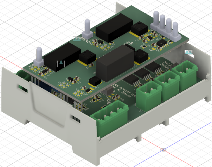
Current voltage input is an open-source printed circuit board by RWTH-ACS, from the RWTH-ACS/current-voltage-input repository on GitHub, published under the CERN-OHL-W-2.0 licence. It is a 2-layer board of 86 × 71 mm with 153 parts on 91 nets, routed with 1,036 tracks and 113 vias.
It is built around the AD8421ARZ, AMC1302DWV and M20-7810245. Its parts include 65 capacitors, 57 resistors, 12 ICs, 10 connectors and 1 inductor.


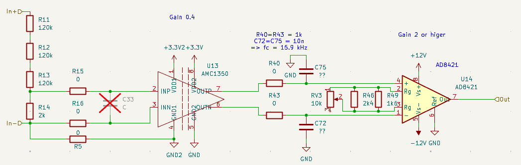
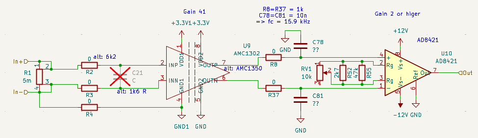
The described device provides three 230 V rated voltage inputs and three current inputs for 5 A nominal. Both are isolated and converted to a +-10V output signal. A detailed explanation is given in the following publication: https://ieeexplore.ieee.org/document/11219915
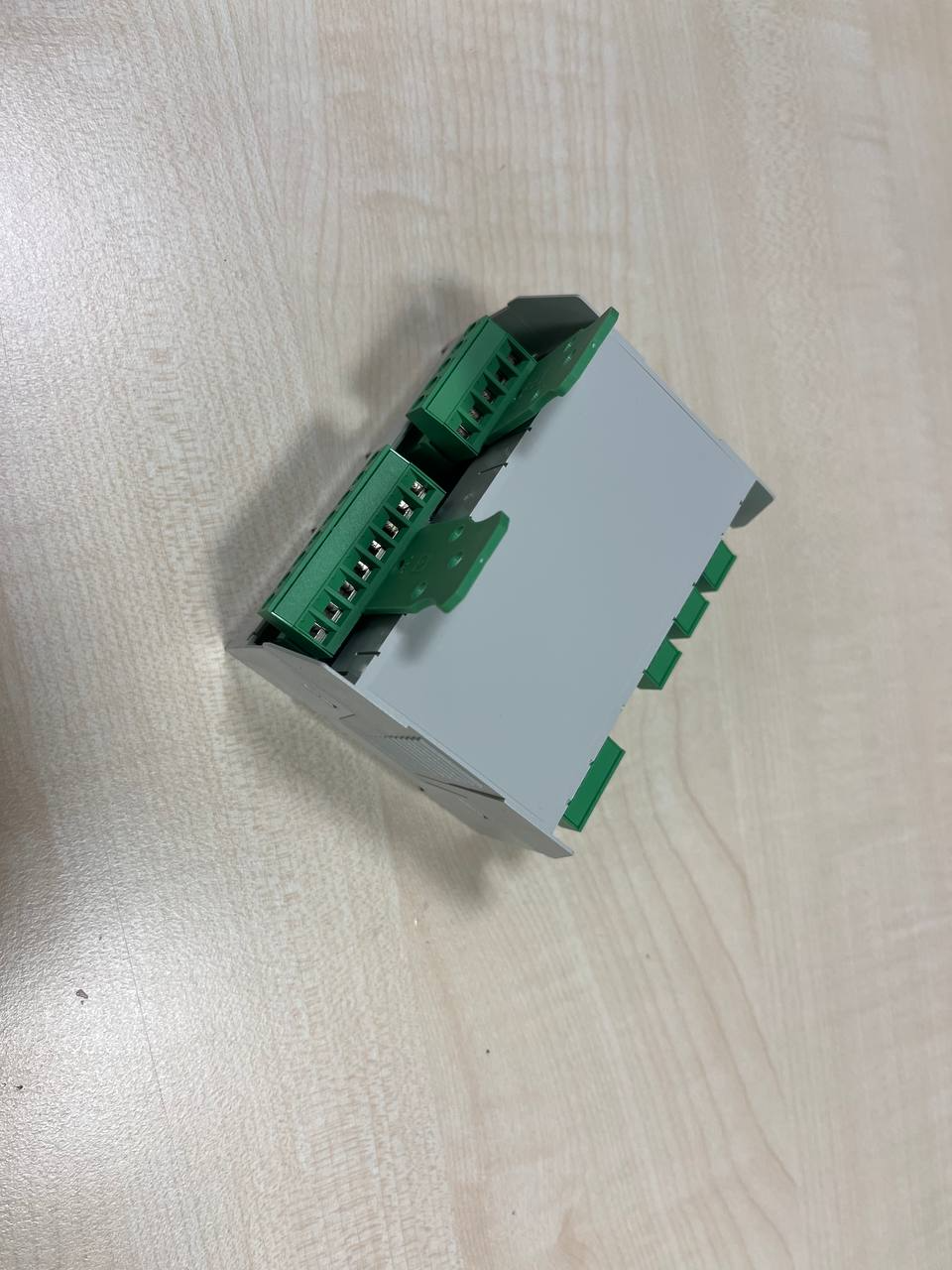
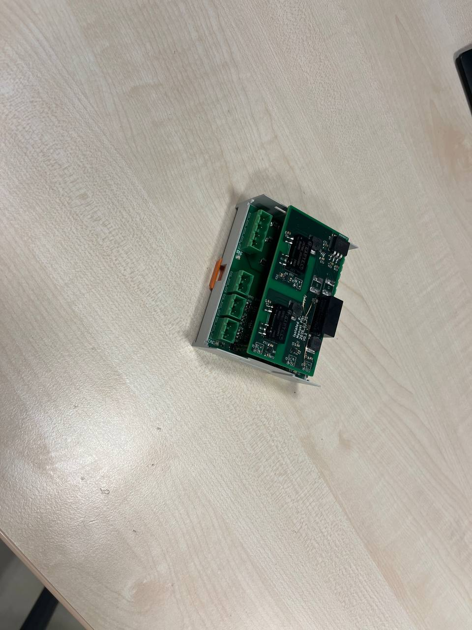
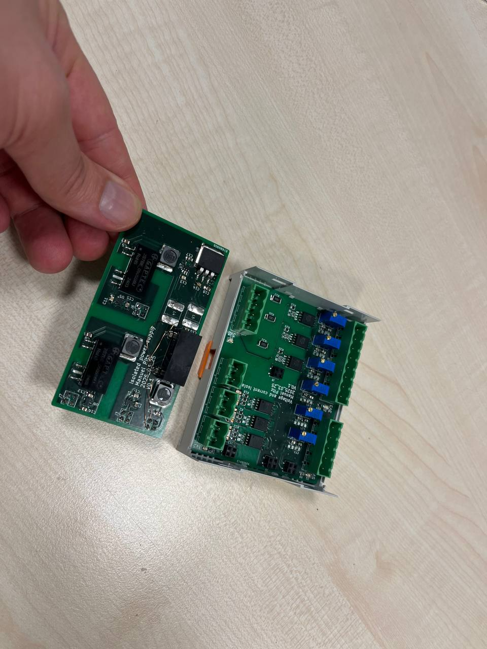
This hardware is licensed unter CERN-OHL-W-2.0 open source license. Please refer to the license file in the LICENSE.
We kindly ask all academic publications employing components of this work to cite the following paper:
For other licensing options please consult Prof. Antonello Monti.

Institute for Automation of Complex Power Systems (ACS) EON Energy Research Center (EONERC) RWTH University Aachen, Germany
This work has been performed in the framework Target-X, a project funded by the Smart Networks and Services Joint Undertaking (SNS JU) under Horizon Europe. The views expressed are those of the authors and do not necessarily represent the project. The consortium is not liable for any use that may be made of any of the information contained therein.
We are grateful for the financial support of the BMWE (Federal Ministry of Economic Affairs and Energy), funding reference 03El6085.

| Qty | Value | Footprint | References |
|---|---|---|---|
| 30 | 0 | Resistor_SMD:R_0805_2012Metric_Pad1.20x1.40mm_HandSolder | R2, R3, R10, R15, R16, R18, R19, R20, R22, R23, R24, R29, R30, R35, R36, R37 +14 |
| 24 | 100n | Capacitor_SMD:C_0805_2012Metric_Pad1.18x1.45mm_HandSolder | C19, C20, C22, C24, C34, C35, C36, C38, C40, C41, C43, C45, C47, C48, C50, C52 +8 |
| 12 | 10n? | Capacitor_SMD:C_0805_2012Metric_Pad1.18x1.45mm_HandSolder | C72, C73, C74, C75, C76, C77, C78, C79, C80, C81, C82, C83 |
| 11 | 10u | Capacitor_SMD:C_0805_2012Metric_Pad1.18x1.45mm_HandSolder | C26, C29, C31, C37, C39, C58, C60, C65, C67, C70, C71 |
| 11 | 1u | Capacitor_SMD:C_0805_2012Metric_Pad1.18x1.45mm_HandSolder | C23, C25, C27, C30, C32, C44, C46, C51, C53, C68, C69 |
| 9 | 120k | Resistor_SMD:R_2010_5025Metric_Pad1.40x2.65mm_HandSolder | R11, R12, R13, R25, R26, R27, R31, R32, R33 |
| 6 | 10k | Potentiometer_THT:Potentiometer_Bourns_3296Y_Vertical | RV1, RV3, RV4, RV5, RV6, RV7 |
| 6 | AD8421 | Package_SO:MSOP-8_3x3mm_P0.65mm | U10, U14, U16, U18, U20, U22 |
| 6 | C | Capacitor_SMD:C_0805_2012Metric_Pad1.18x1.45mm_HandSolder | C21, C33, C42, C49, C54, C61 |
| 4 | M20-7810245 | custom:Harwin_M20-7810245_2x02_P2.54mm_Vertical_Larger_Pads | J7, J8, J9, J13 |
| 3 | 1k6 | Resistor_SMD:R_0805_2012Metric_Pad1.20x1.40mm_HandSolder | R49, R50, R51 |
| 3 | 2k | Resistor_SMD:R_0805_2012Metric_Pad1.20x1.40mm_HandSolder | R14, R28, R34 |
| 3 | 2k4 | Resistor_SMD:R_0805_2012Metric_Pad1.20x1.40mm_HandSolder | R46, R47, R48 |
| 3 | 2k7 | Resistor_SMD:R_0805_2012Metric_Pad1.20x1.40mm_HandSolder | R52, R53, R54 |
| 3 | 47k | Resistor_SMD:R_0805_2012Metric_Pad1.20x1.40mm_HandSolder | R55, R56, R57 |
| 3 | 5m | custom:PEWF | R1, R17, R21 |
| 3 | AMC1302 | custom:DWV | U9, U15, U17 |
| 3 | AMC1350 | custom:DWV | U13, U19, U21 |
| 3 | Conn_01x02_Socket | custom:PhoenixContact_MSTBVA_2,5_2-G-5,08_1x02_P5.08mm_Vertical_alt | J2, J3, J4 |
| 2 | SolderJumper_3_Open | Jumper:SolderJumper-3_P1.3mm_Open_RoundedPad1.0x1.5mm_NumberLabels | JP1, JP2 |
| 1 | Conn_01x04_Socket | custom:PhoenixContact_MSTBVA_2,5_4-G-5,08_1x04_P5.08mm_Vertical_alt | J5 |
| 1 | Conn_01x05_Socket | custom:PhoenixContact_MSTBVA_2,5_5-G-5,08_1x05_P5.08mm_Vertical_alt | J1 |
| 1 | Conn_01x08_Socket | custom:PhoenixContact_MSTBVA_2,5_8-G-5,08_1x08_P5.08mm_Vertical_alt | J6 |
| 1 | nb | Capacitor_SMD:C_0805_2012Metric_Pad1.18x1.45mm_HandSolder | C28 |
| 1 | nb | Inductor_SMD:L_1206_3216Metric_Pad1.42x1.75mm_HandSolder | L2 |
It measures 86 × 71 mm and has 2 copper layers, 1.6 mm thick.
153 parts, built around the AD8421ARZ, AMC1302DWV and M20-7810245. The full list of its parts is on this page, with links to each part's symbol and footprint where PCBKit's library has them.
From the RWTH-ACS/current-voltage-input repository on GitHub, at the commit this page was made from: the board is analog_channels/current-voltage-input.kicad_pcb and its schematic analog_channels/current-voltage-input.kicad_sch. PCBKit opens the board in the browser, with nothing to install.
Its repository publishes it under the CERN-OHL-W-2.0 licence: you may reuse it on that licence's terms (keep the author's notice, and for a copyleft licence share your changes alike).
RWTH-ACS/current-voltage-input
Input Stage for three phase voltage and current in the low voltage grid


abelwu2001/Picosat-Pocketcube-UTN-FRC-2026
Proyecto Final para el armado de un nanoSat


scalinq-lab/cryomagsens
The sensor unit was designed in KiCad 10 and manufactured by JLCPCB. It is built in a flex PCB material to achieve a very small build height, in order to come very close to the device under test.

DylanLockyer/Black_Body
Electrical system for black body MKID tester

AErbsloeh/stimulation_genv3
Hardware Design Files for Experimental Stimulation Platform (Gen 3)