2 layers160 × 120 mm

 rwpeterson/phasefreq2
Phase-frequency detector PCB built around AD9901
Phasefreq is an open-source printed circuit board by rwpeterson, from the rwpeterson/phasefreq repository on GitHub, published under the MIT licence. It is a 4-layer board of 90.5 × 56 mm with 113 parts on 56 nets, routed with 1,481 tracks and 212 vias.
It is built around the AD8676BR, AD9901KP and LM4040DIZ-2.5, with the SLVU2.8-8A1 among its other parts. Its parts include 44 capacitors, 37 resistors, 7 ICs, 4 connectors and 1 diode.


Phase-frequency detector PCB built around the AD9901
A phase-frequency detector (or phase-frequency discriminator) is similar to an analog mixer, in that if the LO and RF frequencies are the same, its output is proportional to the relative phase between them. However, if the LO and RF frequencies differ, a PFD will output a constant voltage whose sign indicates which of the two frequencies is larger. In this case, an analog mixer would produce IF beatnotes at the sum and difference frequencies. This second characteristic of a PFD is useful to more quickly bring a feedback system such as a PLL into lock.
Of course, an analog mixer may be perfectly suitable for your application. More sophisticated PLL ICs contain builtin PFDs as part of the feedback loop. Some evaluation boards expose enough functionality to use them solely as a PFD, but they are prohibitively expensive for many applications where a simple PFD would be beneficial, and often need to be programmed or initialized at the point of use.
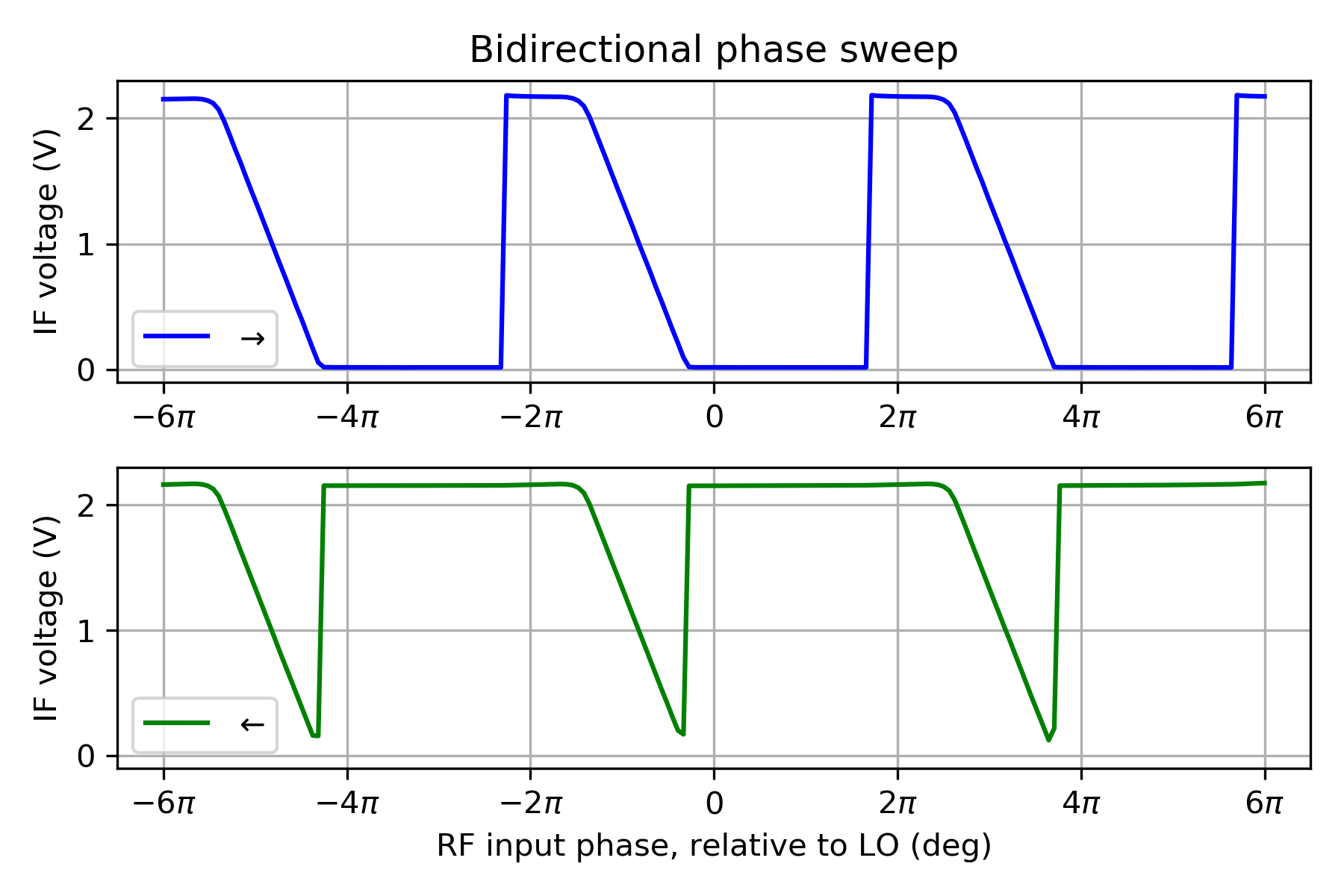
Scanning the relative phase of the inputs demonstrates the linear phase detection and capture range. The location of the linear phase detection is modulo 2 pi as expected. However, when the phase is scanned away from a given phase detection range, the IF output will rail for one additional phase cycle before phase-slipping to the second capture range 4 pi away (as shown). For frequencies > 50 MHz, the ends of the phase detection range will be distorted (see AD9901 datasheet, Fig. 7).
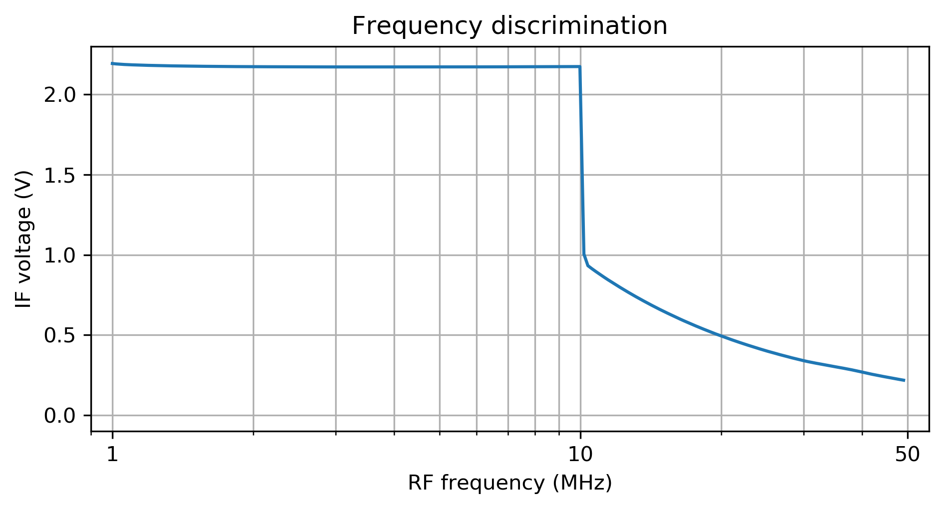
When the RF and LO frequencies differ substantially, the PFD outputs a constant voltage indicating which is higher.
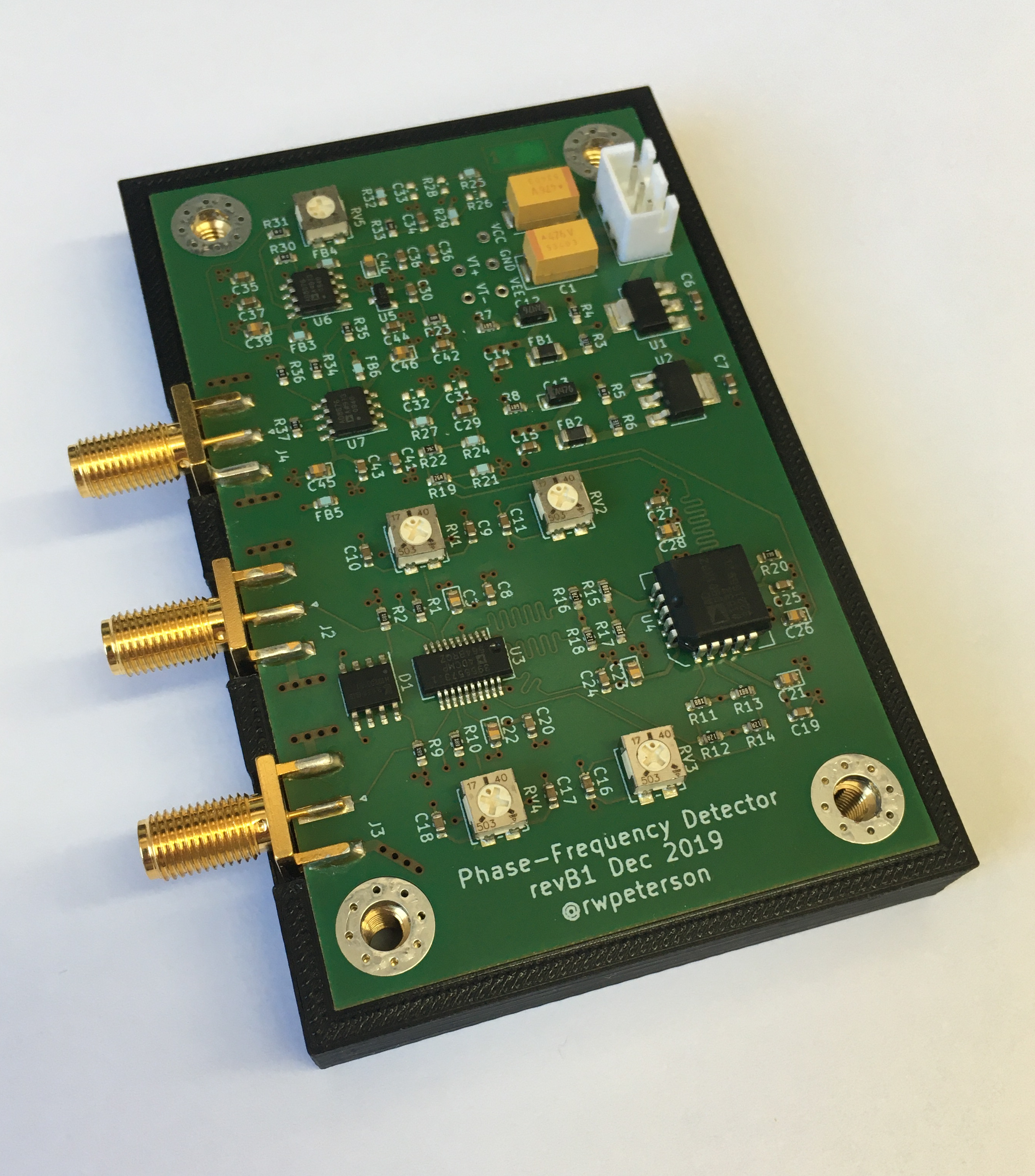
This is the device used for the above characterization plots.
| Qty | Value | Footprint | References |
|---|---|---|---|
| 16 | 100n | Capacitor_SMD:C_0603_1608Metric | C6, C7, C9, C10, C11, C14, C15, C16, C17, C18, C30, C34, C37, C38, C43, C44 |
| 7 | 1K | Resistor_SMD:R_0603_1608Metric | R4, R5, R30, R31, R34, R35, R36 |
| 6 | 10n | Capacitor_SMD:C_0603_1608Metric | C8, C19, C20, C24, C25, C27 |
| 6 | 1u | Capacitor_Tantalum_SMD:CP_EIA-1608-10_AVX-L | C3, C21, C22, C23, C26, C28 |
| 5 | 0R0 | Resistor_SMD:R_0603_1608Metric | R21, R25, R27, R29, R32 |
| 5 | 50K | Potentiometer_SMD:Potentiometer_Vishay_TS53YJ_Vertical | RV1, RV2, RV3, RV4, RV5 |
| 4 | 130 | Resistor_SMD:R_0603_1608Metric | R12, R14, R16, R18 |
| 4 | 1n | Capacitor_SMD:C_0603_1608Metric | C35, C36, C41, C42 |
| 4 | 49R9 | Resistor_SMD:R_0603_1608Metric | R1, R2, R9, R10 |
| 4 | 4u7 | Capacitor_Tantalum_SMD:CP_EIA-1608-10_AVX-L | C39, C40, C45, C46 |
| 4 | 80R6 | Resistor_SMD:R_0603_1608Metric | R11, R13, R15, R17 |
| 4 | BLM18PG221SZ1D | Inductor_SMD:L_0603_1608Metric | FB3, FB4, FB5, FB6 |
| 4 | M4 | MountingHole:MountingHole_4.3mm_M4_Pad_Via | H1, H2, H3, H4 |
| 3 | DNP | Capacitor_SMD:C_0603_1608Metric | C31, C32, C33 |
| 2 | 330 | Resistor_SMD:R_0603_1608Metric | R3, R6 |
| 2 | 47u | Capacitor_Tantalum_SMD:CP_EIA-7343-43_Kemet-X | C1, C4 |
| 2 | 47u | Capacitor_Tantalum_SMD:CP_EIA-3216-18_Kemet-A | C12, C13 |
| 2 | 5R0 | Resistor_SMD:R_0603_1608Metric | R7, R8 |
| 2 | AD8676 | Package_SO:SOIC-8_3.9x4.9mm_P1.27mm | U6, U7 |
| 2 | BLM31PG601SN1L | Inductor_SMD:L_1206_3216Metric | FB1, FB2 |
| 2 | DNP | Resistor_SMD:R_0603_1608Metric | R26, R28 |
| 1 | 110 | Resistor_SMD:R_0603_1608Metric | R24 |
| 1 | 182 | Resistor_SMD:R_0603_1608Metric | R19 |
| 1 | 18K2 | Resistor_SMD:R_0603_1608Metric | R22 |
| 1 | 1K50 | Resistor_SMD:R_0603_1608Metric | R37 |
| 1 | 1u | Capacitor_SMD:C_0603_1608Metric | C29 |
| 1 | 28K | Resistor_SMD:R_0603_1608Metric | R33 |
| 1 | 47R5 | Resistor_SMD:R_0603_1608Metric | R20 |
| 1 | 499R | Resistor_SMD:R_0603_1608Metric | R23 |
| 1 | AD9901 | Package_LCC:PLCC-20 | U4 |
| 1 | ADCMP564 | Package_SO:QSOP-20_3.9x8.7mm_P0.635mm | U3 |
| 1 | GND | TestPoint:TestPoint_THTPad_D1.5mm_Drill0.7mm | GND |
| 1 | LM317_3PinPackage | Package_TO_SOT_SMD:SOT-223-3_TabPin2 | U1 |
| 1 | LM337_SOT223 | Package_TO_SOT_SMD:SOT-223-3_TabPin2 | U2 |
| 1 | LM4040DIZ-2.5 | Package_TO_SOT_SMD:SOT-23 | U5 |
| 1 | LO Input | Connector_Coaxial:SMA_Amphenol_132289_EdgeMount | J3 |
| 1 | Power Input | Connector_JST:JST_XH_B3B-XH-A_1x03_P2.50mm_Vertical | J1 |
| 1 | RF Input | Connector_Coaxial:SMA_Amphenol_132289_EdgeMount | J2 |
| 1 | SLVU2.8-8 | Package_SO:SOIC-8_3.9x4.9mm_P1.27mm | D1 |
| 1 | VCC | TestPoint:TestPoint_THTPad_D1.5mm_Drill0.7mm | VCC |
| 1 | VCO Tune | Connector_Coaxial:SMA_Amphenol_132289_EdgeMount | J4 |
| 1 | VEE | TestPoint:TestPoint_THTPad_D1.5mm_Drill0.7mm | VEE |
| 1 | VT+ | TestPoint:TestPoint_THTPad_D1.5mm_Drill0.7mm | VT+ |
| 1 | VT- | TestPoint:TestPoint_THTPad_D1.5mm_Drill0.7mm | VT- |
It measures 90.5 × 56 mm and has 4 copper layers, 1.6 mm thick.
113 parts, built around the AD8676BR, AD9901KP, LM4040DIZ-2.5 and SLVU2.8-8A1. The full list of its parts is on this page, with links to each part's symbol and footprint where PCBKit's library has them.
From the rwpeterson/phasefreq repository on GitHub, at the commit this page was made from: the board is phasefreq.kicad_pcb. PCBKit opens the board in the browser, with nothing to install.
Its repository publishes it under the MIT licence: you may reuse it on that licence's terms (keep the author's notice, and for a copyleft licence share your changes alike).

Sarbf1/Gas-sens_Rs-485
a compact, cheap gas sensor with RS-485 connectivity

sgenomics/pcbs
There are my personal PCBs... contact me for licensing information.


tinyvision-ai-inc/UPduino-v3.0
UPduino 3.0: new 4 layer layout, various other improvements

westonb/little-bee-B1
A high performance current & magnetic field probe


dmcke5/MiniPC_BMS
An all in one power managment solution for powering mini pc's with batteries!