Skip to the content
PCBKitNew board
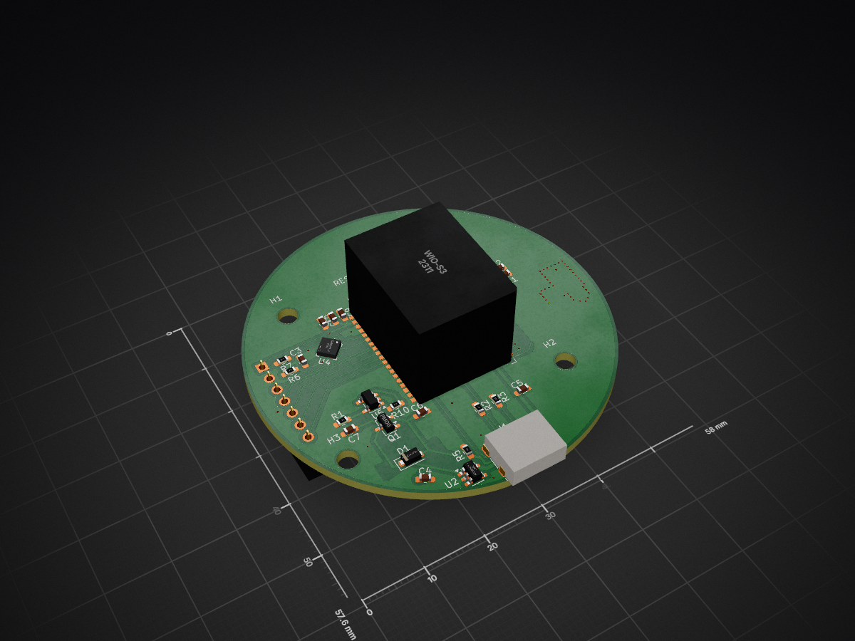
2 layers9 × 57.6 mmTracker, the printed circuit board in 3D
Size
9 × 57.6 mm
Copper layers
2
Thickness
1.6 mm
Parts
44
Nets
67
Pads
196
Tracks, vias
252, 66
Pours
2
Routed
Yes
KiCad
KiCad 10.0 (file 20260206)
Created
31 Jul 2026
Updated
15 Aug 2026

Overview

Tracker is an open-source printed circuit board by RunTheBot, from the RunTheBot/Tracker repository on GitHub. It is a 2-layer board of 9 × 57.6 mm with 44 parts on 67 nets, routed with 252 tracks and 66 vias.

It is built around the MAX-M10S-00B, WIO-S3 and QMC5883P, with the AP2112K-3.3 among its other parts. Its parts include 14 capacitors, 12 resistors, 6 ICs, 3 connectors and 2 switches.

Main components

4

README

README.md

Mesh Tracker

A Mesh Tracker based on Meshtastic, in the form of a compass!

Assembly 1 image image

Features

  • LCD For graphics
  • Battery and Built-In Charger
  • 9 Axis IMU (6 Axis + Magnometer)
  • BLE, WiFi, LoRA
  • Nearby Pairing

How it works

Uses LoRa to transmit to the Meshtastic network on a private channel.

Links

CAD Firmware PCB BOM

Parts

44
QtyValueFootprintReferences
60.1uFCapacitor_SMD:C_0603_1608Metric_Pad1.08x0.95mm_HandSolderC9, C10, C11, C12, C13, C14
54.7uFCapacitor_SMD:C_0603_1608Metric_Pad1.08x0.95mm_HandSolderC3, C4, C5, C6, C7
410kResistor_SMD:R_0603_1608Metric_Pad0.98x0.95mm_HandSolderR5, R10, R11, R12
44.7kResistor_SMD:R_0603_1608Metric_Pad0.98x0.95mm_HandSolderR6, R7, R8, R9
4MountingHoleMountingHole:MountingHole_3.2mm_M3H1, H2, H3, H4
25.1kResistor_SMD:R_0603_1608Metric_Pad0.98x0.95mm_HandSolderR2, R3
2DNPCapacitor_SMD:C_0402_1005Metric_Pad0.74x0.62mm_HandSolderC1, C2
2SW_PushButton_Switch_SMD:SW_SPST_TS-1088-xR020SW1, SW2
10Resistor_SMD:R_0402_1005Metric_Pad0.72x0.64mm_HandSolderR4
110uFCapacitor_SMD:C_0603_1608Metric_Pad1.08x0.95mm_HandSolderC8
12kResistor_SMD:R_0603_1608Metric_Pad0.98x0.95mm_HandSolderR1
13310472210,IPE-X IPX,lcsc_footprints:C88374_RF-SMD_FRF05002-JSS103MJP1
1AP2112K-3.3Package_TO_SOT_SMD:SOT-23-5U2
1Conn_01x02Connector_JST:JST_PH_S2B-PH-K_1x02_P2.00mm_HorizontalJ2
1DISPLAYConnector_PinSocket_2.54mm:PinSocket_1x07_P2.54mm_VerticalJ3
1D_SchottkyDiode_SMD:D_SOD-123FD1
1LSM6DSV32XTRlcsc_footprints:C22461202_LGA-14L_L3_0-W2_5-P0_50-TLU6
1MAX-M10S-00Blcsc_footprints:C4153167_SMD-18_L10_1-W9_7-P1_10-TL_SKG09FU3
1MCP73812T-420I-OTPackage_TO_SOT_SMD:SOT-23-5U5
1PMOSPackage_TO_SOT_SMD:SOT-23-3Q1
1QMC5883Plcsc_footprints:C2847467_LGA-16_L3_0-W3_0-P0_50-BL_SQU4
1USB_C_Receptacle_USB2.0_16PConnector_USB:USB_C_Receptacle_G-Switch_GT-USB-7010ASVJ1
1Wio-S3Wio-S3_Wireless_Module_Kicad_File:Wio-S3 Wireless Module Hand SolderU1

Questions

How big is the Tracker PCB?

It measures 9 × 57.6 mm and has 2 copper layers, 1.6 mm thick.

What parts does the Tracker use?

44 parts, built around the MAX-M10S-00B, WIO-S3, QMC5883P and AP2112K-3.3. The full list of its parts is on this page, with links to each part's symbol and footprint where PCBKit's library has them.

Where can I download the Tracker KiCad files?

From the RunTheBot/Tracker repository on GitHub, at the commit this page was made from: the board is PCB/tracker/tracker.kicad_pcb and its schematic PCB/tracker/tracker.kicad_sch. PCBKit opens the board in the browser, with nothing to install.

Can I use the Tracker design in my own project?

Its repository states no licence, so its author keeps all rights: ask RunTheBot before reusing the design.

Similar boards

  • 4 layers25.4 × 25.4 mmZeo1.2 devboard, the printed circuit board in 3D

    Zeo1.2 devboard

    zeodotdev/zeo-boards

    ESP32-S3 development board with onboard BME280 (temperature, humidity, pressure) and LSM6DS3 (6-axis IMU) sensors. This repo contains the designs, ESP-IDF firmware, and a Python plotter for visualization.

    92 parts3
  • 2 layers94 × 94 mm3axis magnitometer, the printed circuit board in 3D

    3axis magnitometer

    NarodniySputnik/Gladiolus-1

    Gladiolus-1 - автономный модуль для приема и передачи изображений в формате SSTV (Slow Scan TeleVision) на малом космическом аппарате (МКА) формата CubeSat

    96 parts9GPL-3.0
  • 8 layers22.3 × 77.5 mmTinker mantis, the printed circuit board in 3D

    Tinker mantis

    Tinkerbug-Robotics/TinkerRocket

    Model rocket flight computer, ground station, iOS app, and simulation

    279 parts1GPL-3.0
  • 2 layers50 × 50 mmBoreas, the printed circuit board in 3D

    Boreas

    darshg321/Boreas

    an STM32F7 flight controller for a rocket.

    100 parts
  • 4 layers37 × 37 mmNSSFC, the printed circuit board in 3D

    NSSFC

    Keyaan-07/NSSFC

    NSSFC is an FPV flight controller made with the STM32F405 and it has an IMU, Barometric pressure sensor and a magnetometer. It uses the betaflight as firmware(thus no firmware directory in this repository).

    97 parts
  • 4 layers59.5 × 117 mmTaz Main PCB V1.14, the printed circuit board in 3D

    Taz Main PCB V1.14

    root-applied-sciences/Taz-Main-PCB-V1.14

    113 parts
  • 2 layers68.7 × 64.9 mmSpindlyVR, the printed circuit board in 3D

    SpindlyVR

    SpindlySpider/spindlyVR

    65 partsGPL-3.0
  • 2 layers45 × 48 mmAetherpose custom, the printed circuit board in 3D

    Aetherpose custom

    thousandflame1000/aetherpose

    2026-10-18。已選方向:沿用 Arduino Nano 33 BLE 原版 ABX00030/帶針 ABX00034(LSM9DS1),製作供電與固定底板;六個穿戴位置各用一套。

    44 parts