2 layers68.6 × 53.3 mm
Yamabiko a
airpocket-soundman/chikuwa-flute-robot
学習では、あらかじめ作った 1,000 曲のセット(runs/targetbank.npz、trainresiduales.py --bank 1000 で自動作成)から毎世代 8 曲を選んで使い回します。評価用の曲は別の乱数で作るので、学習用と重なりません。セットの中身は WAV と図で確認できます:
44 parts
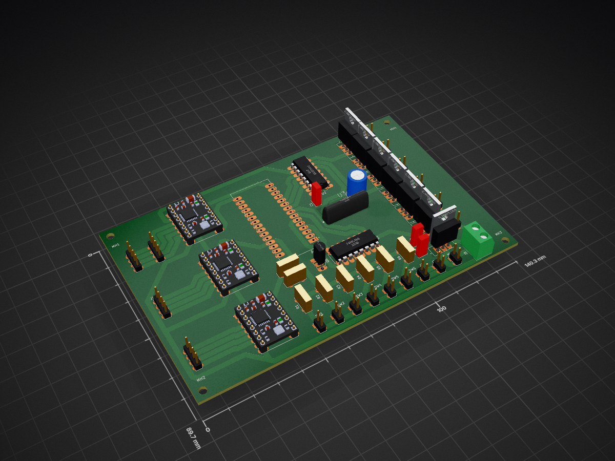
 Ruchi12377/AutoEraser
選択範囲を左上を基準とし01で表す。真ん中から右下まで選択した場合、Start = (0.5, 0.5) End = (1, 1)となる。
AutoEraser is an open-source printed circuit board by Ruchi12377, from the Ruchi12377/AutoEraser repository on GitHub. It is a 2-layer board of 140.3 × 89.7 mm with 51 parts on 91 nets, routed with 492 tracks and 0 vias.
It is built around the TB6643KQ,8, 74HC165D and 74HC595. Its parts include 8 resistors, 8 transistors, 8 connectors, 6 switches and 5 diodes.


はじめに
概要
開発環境
システムの概要
コンポーネント
Camera
Image
KeystoneCorrection
WhiteBoard (Feature)
Select
Erase (Feature)
MoveInitial
InitialSetting
Pump
Move (Feature)
Serial
我々はRTミドルウェアを用いて、ホワイトボードの文字を自動で消すシステムを開発している。本稿では、本システムの改善について述べる。昨年のシステムとの相違点は主に三点ある。一つ目は、材質を木材からアルミニウムに変更することで歪みを解消し、スムーズな可動と軽量化を図ったことである。二つ目は消したい領域をより細かく指定可能にすることで、本来消すべきではない部分を消してしまうことを防げるようになったことである。三つ目は水が入ったタンクを設置し、自動で白板を濡らすことができるようになったため、雑巾を取り外して濡らす必要がなくなったことである。
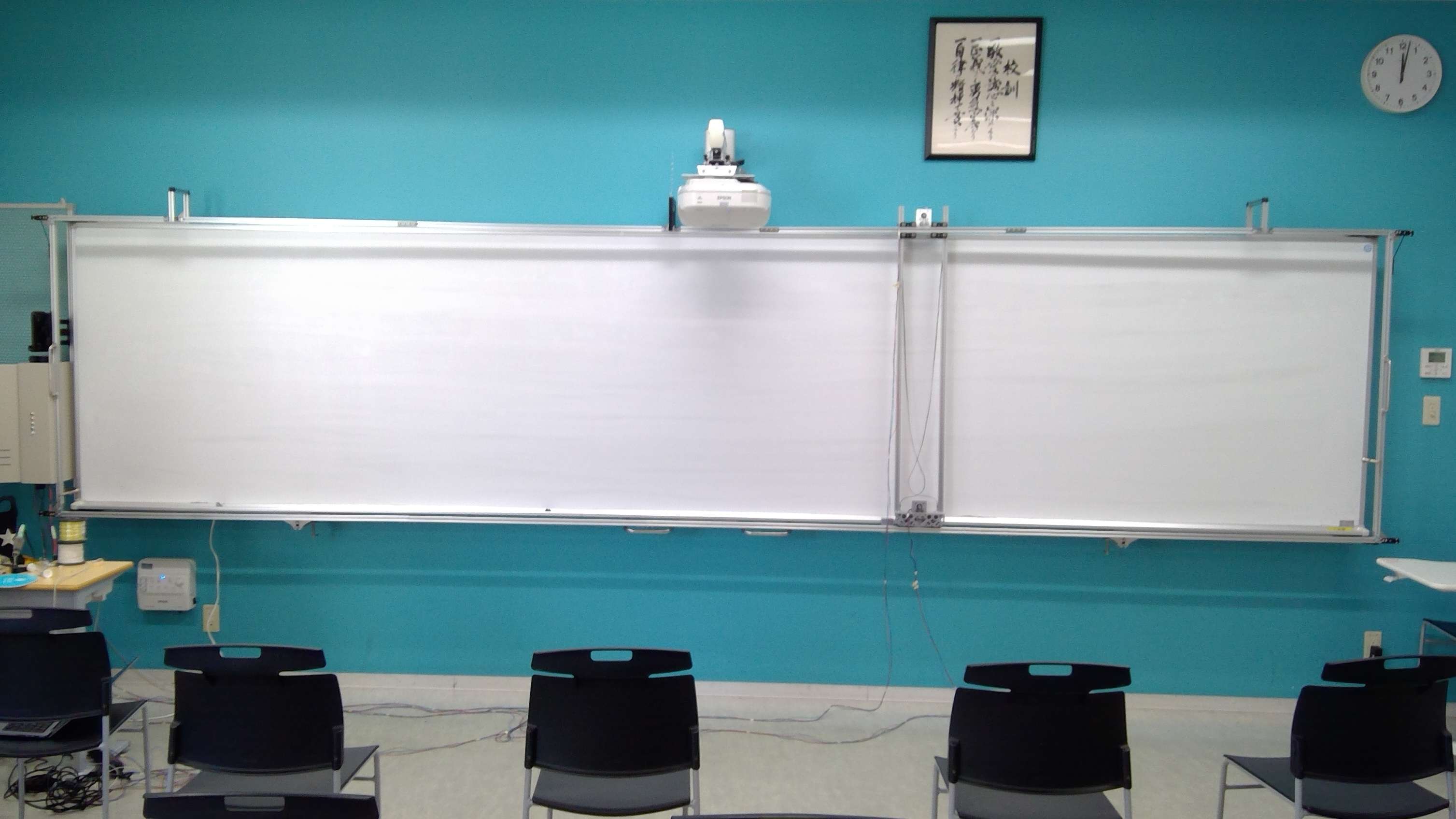
自動ホワイトボード消しのイメージ
本コンポーネント群の開発環境を以下に示す。
| OS | Windows10 |
|---|---|
| RTミドルウェア | OpenRTM-aist-2.0.0-RELESE(Python 版) |
| 開発環境 | VSCode |
| Python | 3.8.5 |
| 必要モジュール | math, numpy, cv2, PIL, sys, time, tkinter |
このシステムは、ユーザーの指定した範囲もしくは、全範囲(全部消す)をレールや枠組みに沿って本体が移動し自動でホワイトボードに書かれたものを消すものである。
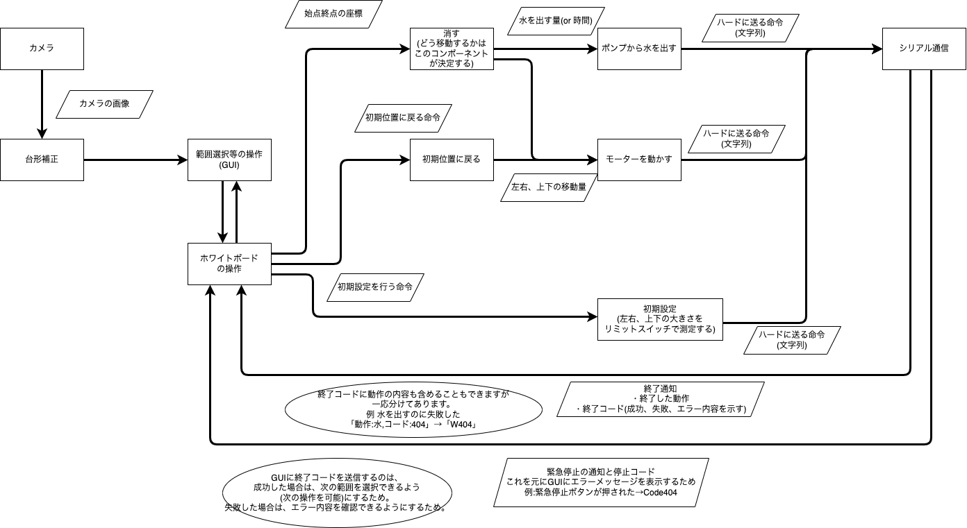
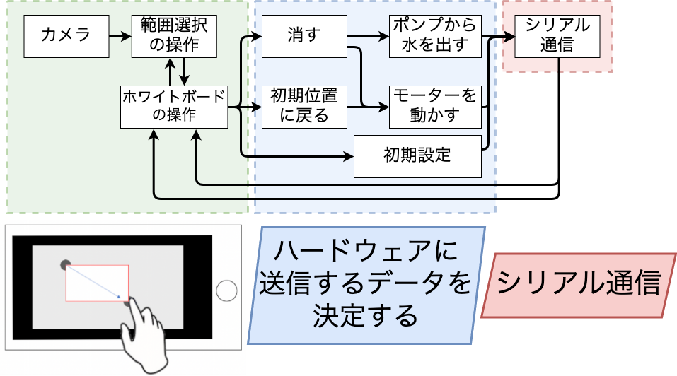
そして、制御部分にはRTミドルウェアを用いており、Cameraコンポーネントを用いて取得したホワイトボードの動画(画像)をSelectコンポーネントで消す範囲を選択し、Eraseコンポーネントでどのように移動するか決定することでMoveコンポーネントが移動するためのコマンドを生成し、Serialコンポーネントを用いてハードウェアに移動するデータをもちいて実際に動かす。というものである。
以下の2つのコンポーネント図を示す。
1.詳しく説明してあるコンポーネント図
2.簡潔化しまとまりごとに色分けしたコンポーネント図
カメラから取得した画像を出力するコンポーネント。
コンフィギュレーションから使用するカメラのインデックスを設定することができる。
InPort
OutPort
| 名称 | データ型 | 説明 |
|---|---|---|
| image | RTC::CameraImage | カメラから取得した画像を出力する。 |
Configuration
| 名称 | データ型 | 説明 | 初期値 | 制限 |
|---|---|---|---|---|
| CameraIndex | short | 使用するカメラのインデックスを設定する。 | 0 | 0<=x<=5 |
コンフィギュレーションで指定されたパスの画像をポートから出力するコンポーネント。
デバックする際、Cameraコンポーネントの代わりに使用することを想定している。
InPort
OutPort
| 名称 | データ型 | 説明 |
|---|---|---|
| Image | RTC::CameraImage | コンフィギュレーションで指定されたパスの画像を出力する。 |
Configuration
| 名称 | データ型 | 説明 | 初期値 | 制限 |
|---|---|---|---|---|
| Path | string | 出力する画像のパス | Emprt String | Undefined |
台形補正をするコンポーネント。
GUIに画像が表示されており、4隅をクリックすることで台形補正を行う。
ホワイトボードをカメラで撮影しなぞるようにして選択するが、その際ホワイトボードの画像は斜めになっているのでこのコンポーネントが必要。
| 名称 | データ型 | 説明 |
|---|---|---|
| ImageIn | RTC::CameraImage | 台形補正をする画像 |
| 名称 | データ型 | 説明 |
|---|---|---|
| ImageOut | RTC::CameraImage | 台形補正済みの画像 |
実装予定
範囲選択をし、選択した矩形の座標を出力するコンポーネント。
選択範囲を左上を基準とし0~1で表す。真ん中から右下まで選択した場合、Start = (0.5, 0.5) End = (1, 1)となる。
Camera Image Select の3つに加え画像切り取りコンポーネントを作成することで画像切り取りができるコンポーネント群をかんたんに作れる。
InPort
| 名称 | データ型 | 説明 |
|---|---|---|
| ShowImage | CameraImage | 選択する際の背景の画像 |
| CompeteMotion | TimedString | 終了した動作名 |
| StatusCode | TimedUShort | ステータスコード |
OutPort
| 名称 | データ型 | 説明 |
|---|---|---|
| StartPos | RTC::TimedPoint2D | 指定された範囲の始点 |
| EndPos | RTC::TimedPoint2D | 指定された範囲の終点 |
Configuration
| 名称 | データ型 | 説明 | 初期値 | 制限 |
|---|---|---|---|---|
| Width | int | 選択ウィンドウの横幅 | 800 | 400<=x<=1600 |
| Height | int | 選択ウィンドウの高さ | 450 | 225<=x<=900 |
選択された範囲を元に消すためのパスを決定するコンポーネント。
InPort
| 名称 | データ型 | 説明 |
|---|---|---|
| StartPos | RTC::TimedPoint2D | 指定された範囲の始点 |
| EndPos | RTC::TimedPoint2D | 指定された範囲の終点 |
OutPort
| 名称 | データ型 | 説明 |
|---|---|---|
| MovePath | TimedStringSeq | x:yの形式で移動する座標のデータを出力する |
Configuration
| 名称 | データ型 | 説明 | 初期値 | 制限 |
|---|---|---|---|---|
初期位置(左上)に本体を移動させるコンポーネント。
移動しきったかの検出にはリミットスイッチを用いる。
InPort
| 名称 | データ型 | 説明 |
|---|---|---|
| MoveToInitial | RTC::Time | 初期位置に戻るタイミングを指定 |
OutPort
| 名称 | データ型 | 説明 |
|---|---|---|
| Command | RTC::TimedString | 初期位置に戻るためのコマンドを生成 |
Configuration
| 名称 | データ型 | 説明 | 初期値 | 制限 |
|---|---|---|---|---|
| TimeOut | int | 移動完了せずタイムアウトする時間 | -1 | -1<=x<=60 |
本体のサイズ、ホワイトボードの横幅をリミットスイッチを用いて検出するコンポーネント。
単位はステッピングモーターの回転数。
InPort
| 名称 | データ型 | 説明 |
|---|---|---|
| Setting | RTC::Time | 検出するタイミング |
OutPort
| 名称 | データ型 | 説明 |
|---|---|---|
| Command | RTC::TimedString | 初期設定を行うためのコマンドを生成 |
Configuration
| 名称 | データ型 | 説明 | 初期値 | 制限 |
|---|---|---|---|---|
指定された量の水をポンプから出すコンポーネント。
単位はmL
InPort
| 名称 | データ型 | 説明 |
|---|---|---|
| WaterAmount | RTC::TimedUShort | ポンプから出す水の量 |
OutPort
| 名称 | データ型 | 説明 |
|---|---|---|
| PumpWaterAmount | RTC::TimedString | ポンプから水を出すためのコマンド |
Configuration
| 名称 | データ型 | 説明 | 初期値 | 制限 |
|---|---|---|---|---|
| Amou |
パスを元に、モーターを動かすためのコマンドを生成するコンポーネント。
InPort
| 名称 | データ型 | 説明 |
|---|---|---|
| Command | RTC::TimedPoint2D | モーターを動かすための座標 |
OutPort
| 名称 | データ型 | 説明 |
|---|---|---|
| Command | RTC::TimedString | ハードウェアに送信するコマンド |
Configuration
| 名称 | データ型 | 説明 | 初期値 | 制限 |
|---|---|---|---|---|
シリアル通信のRead/Writeを行うコンポーネント。
InPort
| 名称 | データ型 | 説明 |
|---|---|---|
| Write | RTC::TimedString | シリアル通信で書き込むデータ |
OutPort
| 名称 | データ型 | 説明 |
|---|---|---|
| Read | RTC::TimedString | シリアル通信で読み込んだデータ |
Configuration
| 名称 | データ型 | 説明 | 初期値 | 制限 |
|---|---|---|---|---|
| Path | string | シリアル通信を行うデバイスのパス | EmptyString | |
| Boundrate | int | シリアル通信を行うための速度 | 9600 | Undefined |
| Qty | Value | Footprint | References |
|---|---|---|---|
| 7 | Q_NMOS_GDS | 2sk2232:TO254P1054X470X1955-3 | Q1, Q2, Q3, Q4, Q5, Q6, Q7 |
| 6 | SW_Push | Connector_PinHeader_2.54mm:PinHeader_1x02_P2.54mm_Vertical | SW1, SW2, SW3, SW4, SW5, SW6 |
| 6 | z | Resistor_THT:R_Box_L8.4mm_W2.5mm_P5.08mm | R1, R2, R3, R4, R5, R6 |
| 5 | LED | Connector_PinHeader_2.54mm:PinHeader_1x02_P2.54mm_Vertical | D1, D2, D3, D4, D5 |
| 4 | Conn_01x04 | Connector_PinHeader_2.54mm:PinHeader_1x04_P2.54mm_Vertical | J1, J2, J3, J4 |
| 4 | MountingHole_3.2mm_M3 | MountingHole:MountingHole_3.2mm_M3 | MH1, MH2, MH3, MH4 |
| 3 | C | Capacitor_THT:C_Rect_L4.0mm_W2.5mm_P2.50mm | C1, C3, C4 |
| 3 | Pololu_Breakout_A4988 | A4988_STEPPER_MOTOR_DRIVER_CARRIER:MODULE_A4988_STEPPER_MOTOR_DRIVER_CARRIER | A1, A2, A3 |
| 2 | Actuator | Connector_PinHeader_2.54mm:PinHeader_1x02_P2.54mm_Vertical | J6, J7 |
| 2 | R | Resistor_THT:R_Box_L8.4mm_W2.5mm_P5.08mm | R7, R8 |
| 1 | 74HC165 | Package_DIP:DIP-16_W7.62mm | U1 |
| 1 | 74HC595 | Package_DIP:DIP-16_W7.62mm | U2 |
| 1 | Arduino_Micro | ARDUINO_NANO:SHIELD_ARDUINO_NANO | A4 |
| 1 | C | Capacitor_THT:C_Radial_D8.0mm_H11.5mm_P3.50mm | C2 |
| 1 | Fan | Connector_PinHeader_2.54mm:PinHeader_1x02_P2.54mm_Vertical | M1 |
| 1 | Pump | Connector_PinHeader_2.54mm:PinHeader_1x02_P2.54mm_Vertical | J5 |
| 1 | Q_NPN_ECB | Package_TO_SOT_THT:TO-92L_Inline_Wide | Q8 |
| 1 | Screw_Terminal_01x02 | TerminalBlock:TerminalBlock_bornier-2_P5.08mm | J8 |
| 1 | TB6643KQ | TB6643KQ:SIP1005W50P254L1965H1265Q7 | U3 |
airpocket-soundman/chikuwa-flute-robot
学習では、あらかじめ作った 1,000 曲のセット(runs/targetbank.npz、trainresiduales.py --bank 1000 で自動作成)から毎世代 8 曲を選んで使い回します。評価用の曲は別の乱数で作るので、学習用と重なりません。セットの中身は WAV と図で確認できます:


slu4coder/Minimal-64x4-Home-Computer
My DIY TTL home computer with VGA and PS/2 and 4x the processing power of a Commodore C64 or Apple II.

westlicht/performer-hardware
PER|FORMER Eurorack Sequencer - Hardware Design Files

slu4coder/Minimal-64-Home-Computer
Legacy: Full TTL-only home computer with VGA and PS/2 and twice the processing power of a Commodore 64

slu4coder/Minimal-UART-Computer-3
Version 3 of my educational DIY TTL computer built around a UART serial interface - now with blinkenlights!
It measures 140.3 × 89.7 mm and has 2 copper layers, 1.6 mm thick.
51 parts, built around the TB6643KQ,8, 74HC165D and 74HC595. The full list of its parts is on this page, with links to each part's symbol and footprint where PCBKit's library has them.
From the Ruchi12377/AutoEraser repository on GitHub, at the commit this page was made from: the board is WB/WB.kicad_pcb and its schematic WB/Cane/Cane.kicad_sch. PCBKit opens the board in the browser, with nothing to install.
Its repository states no licence, so its author keeps all rights: ask Ruchi12377 before reusing the design.