2 layers390 × 37 mm
ButtonsLEDs
shanteacontrols/OpenDeck
A platform for building interactive control and sensing devices using MIDI and OSC built with Zephyr RTOS.
100 parts960Apache-2.0

 rschenk/egret43
36 key choc hotswap keyboard, wireless, very thin
Egret is an open-source printed circuit board by rschenk, from the rschenk/egret repository on GitHub, published under the MIT licence. It is a 2-layer board of 223.1 × 94.9 mm with 100 parts on 69 nets, routed with 617 tracks and 12 vias.
Its parts include 47 diodes and 36 switches. It belongs with the keyboards and input boards of this library.
A 36 key Choc-spaced monoblock keyboard that's wireless compatible, hot swappable, gasket mounted, and very thin. Inspired by the chocV and Horizon.
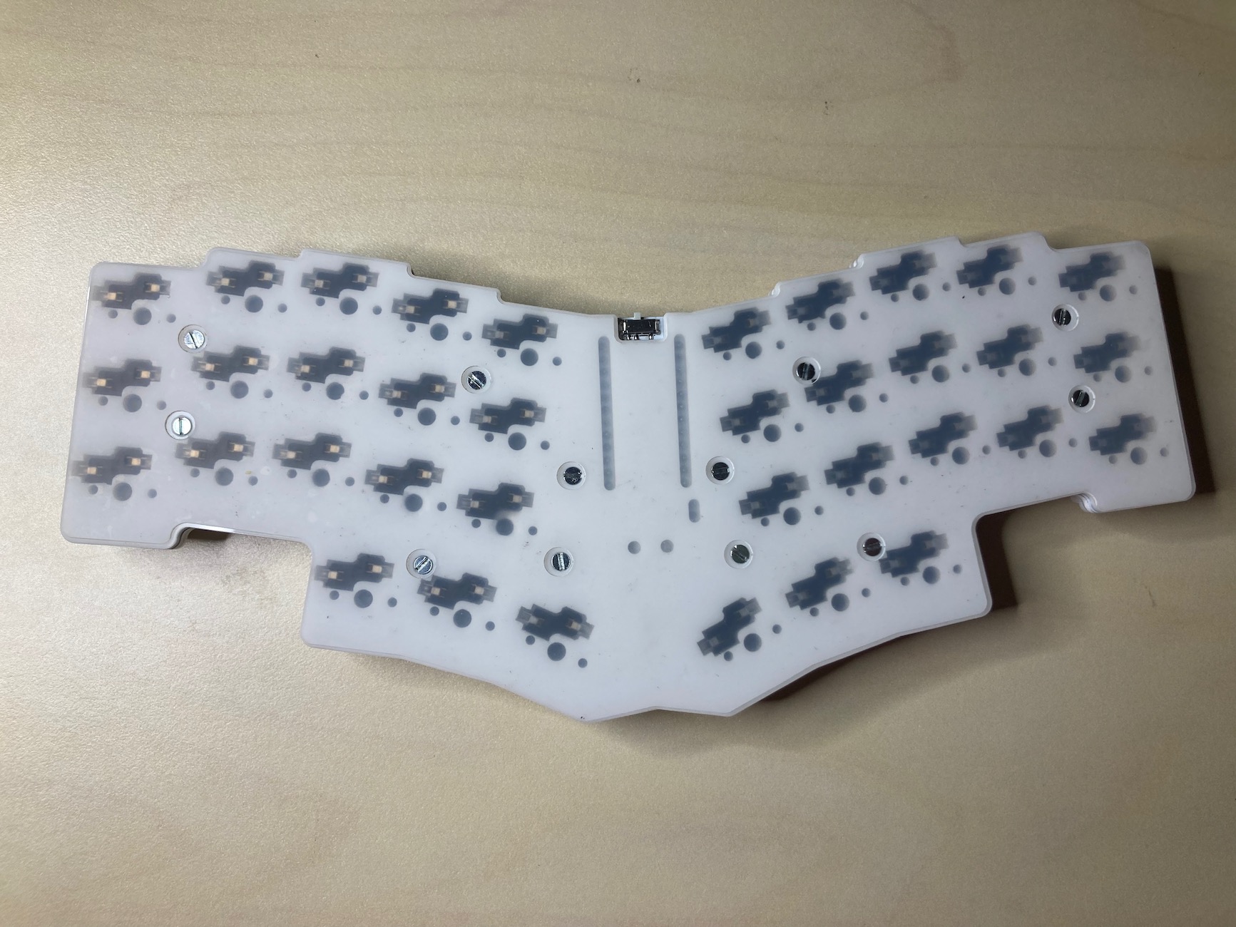
The Egret's bottom plate has cutouts for the hotswap sockets, essentially the thinnest board possible with hotswap sockets. Silicone gaskets sandwiching both sides of the PCB dampen sounds and vibrations. The entire bottom is covered with rubber sheet so you can use it right on your laptop keys if you're so inclined!
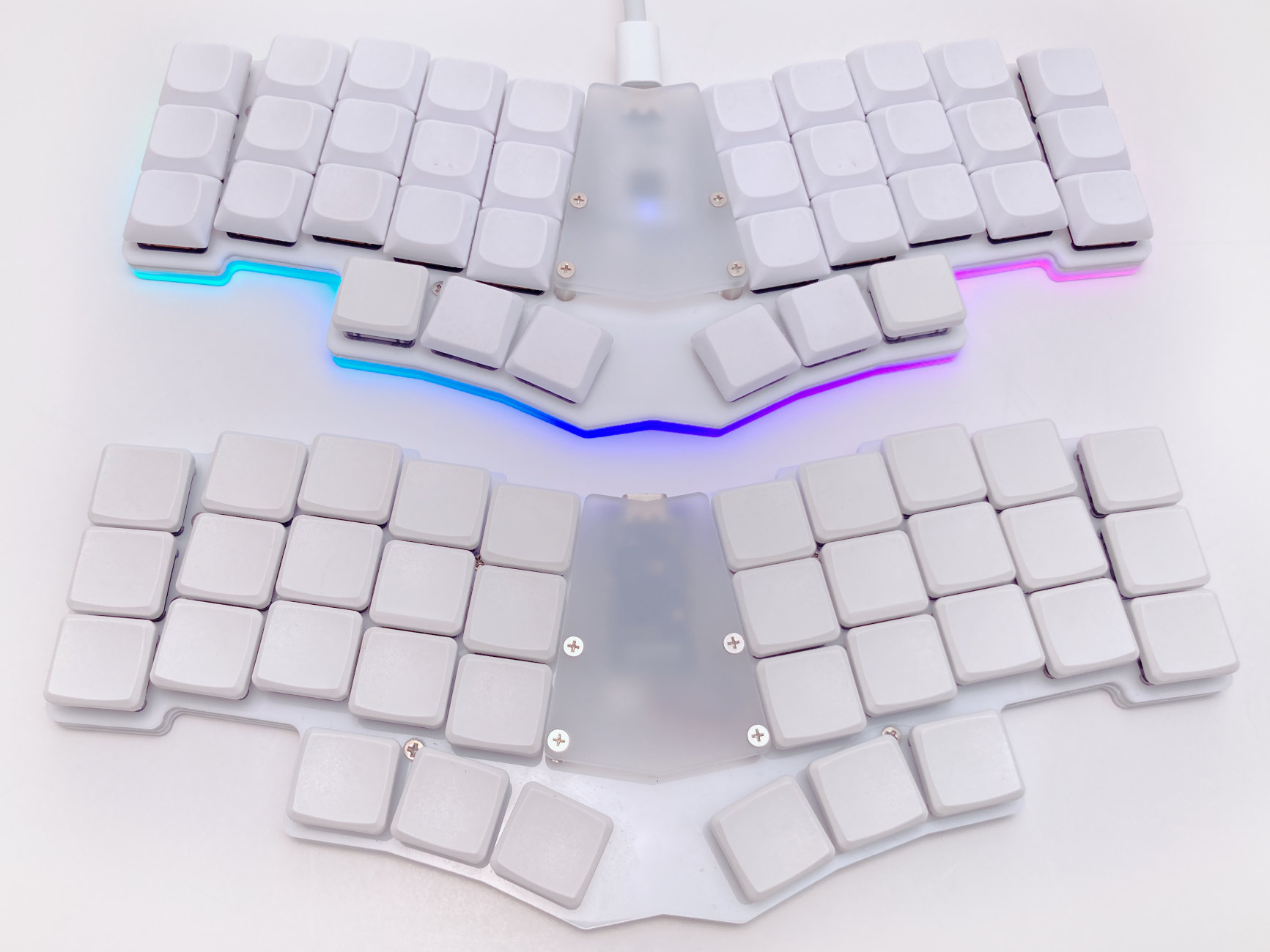
The bottom plate is cut out to accomodate the hotswap sockets, making it about as thin as is physically possible to make a hotswap board. The entire bottom is intended to be covered with rubber, sililicone, EVA, etc, so you can put it down on right over your laptop's keys. Yes this actually works and is useable!
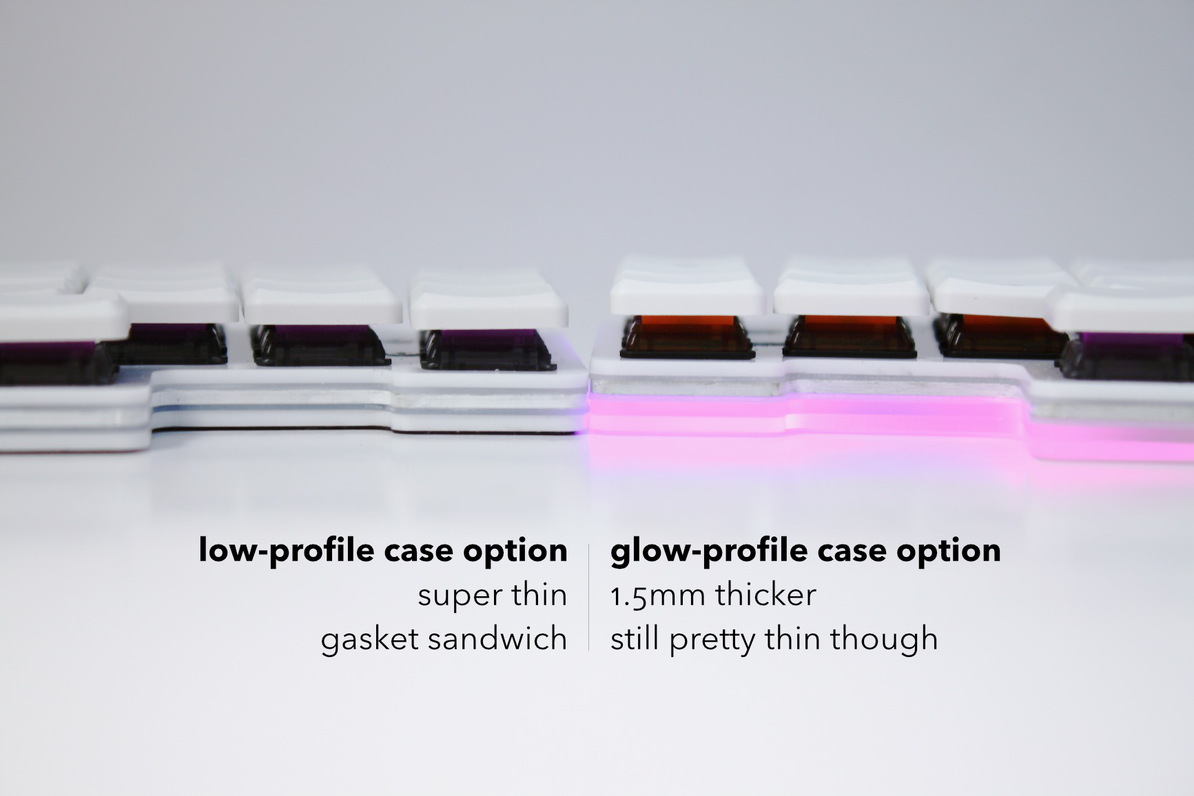
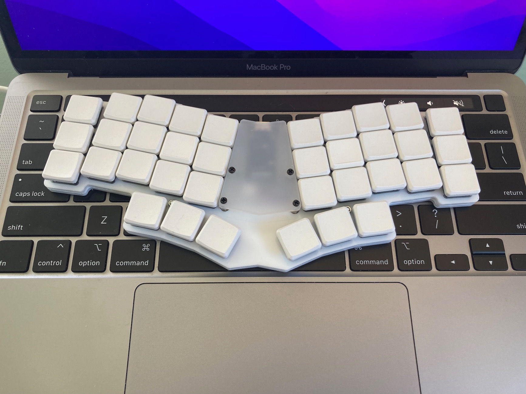
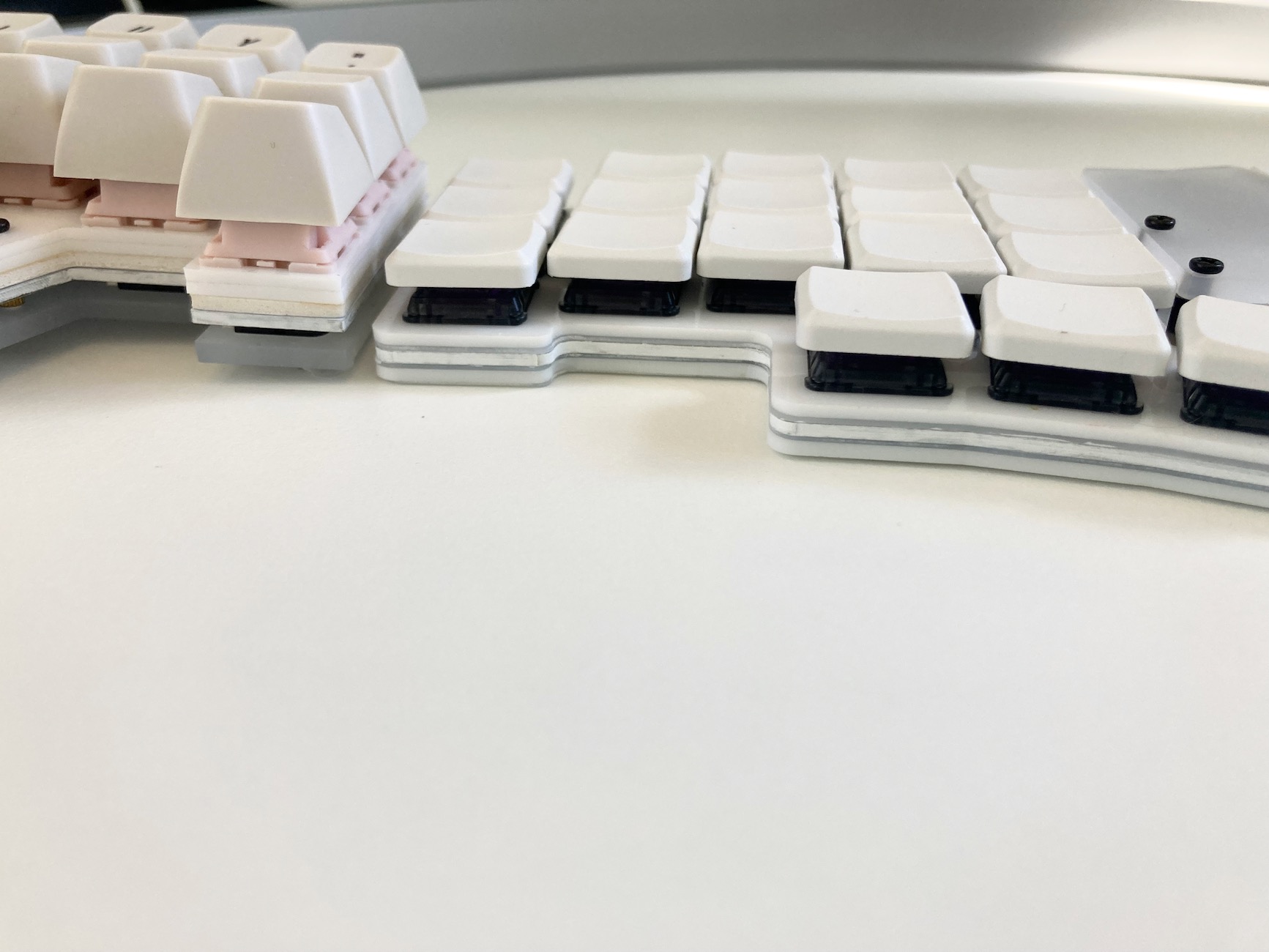
There are two ways to build it, with LED underglow (glow-profile case) and without (low profile case). The LED version requires a different bottom plate which is 1.5mm taller than the low-profile version, but everything else is the same between them—same PCB, top plate, gaskets, etc. Either version can be used with bluetooth! Obviously running the LEDs will drain your battery much faster, but it's easy to have the best of both worlds by configuring ZMK to automatically enable LEDs when plugged into USB and disable them when on battery power.
Egret is not in the main QMK repo yet (or probably ever) but it's easy to add to your local.
Assuming you already have QMK set up on your computer, copy the contents of ./firmware/qmk to qmk_firmware/keyboards/egret. There is a very minimal basic keymap for you to start with.
cp -R ./firmware/qmk /path/to/qmk_firmware/keyboards/egret
cd !$
cp -R keymaps/default keymaps/your-github-usernameEgret is not in the main ZMK repo but it's easy to add. Assuming you already have a zmk-config setp already, copy the contents of ./firmware/zmk to zmk-config/config/boards/shields/egret, then make the usual setup. There is a basic minimal keymap for you to start with.
cp -R ./firmware/zmk /path/to/zmk-config/config/boards/shields/egret
cd /path/to/zmk-config/config
cp boards/shields/egret/egret.keymap .
touch egret.confThis board is generated with the amazing ergogen tool, then post-processed with KiCad and vector graphics drawing tools. I used several custom footrpints to pull off the "horizon construction" on the bottom plate. Since ergogen does not currently support adding footprints at runtime, I Dockerized it and copied my footprints into the image. The Dockerfile lives in ergogen/container and can be run with a little wrapper script I wrote in ergogen/bin/ergogen.
To generate the board (which you should not need to unless you want to change something):
$ cd ergogen
$ bin/ergogen egret.yml
If you decide to edit a footprint, you'll need to remove the image and rebuild it.
# Only if you modify a footprint, rebuild the image like so:
$ docker image rm -f ergogen-egret && bin/ergogen egret.yml| Qty | Value | Footprint | References |
|---|---|---|---|
| 36 | PG1350 | S1, S2, S10, S11, S12, S13, S14, S15, S16, S17, S18, S19, S20, S21, S22, S23 +20 | |
| 36 | ComboDiode | D1, D2, D10, D11, D12, D13, D14, D15, D16, D17, D18, D19, D20, D21, D22, D23 +20 | |
| 12 | MountingHole_2.2mm_M2_Pad | PAD2, PAD3, PAD4, PAD5, PAD6, PAD7, PAD8, PAD9, PAD10, PAD11, PAD12, PAD13 | |
| 11 | VAL** | WS2812B | LED1, LED2, LED3, LED4, LED5, LED6, LED7, LED8, LED9, LED10, LED11 |
| 1 | ResetSW_1side | B1 | |
| 1 | ProMicroPadCutouts | PAD1 | |
| 1 | E73:SPDT_C128955 | T1 | |
| 1 | JST_PH_S2B-PH-K_02x2.00mm_Angled | JST1 | |
| 1 | ProMicro | MCU1 |
It measures 223.1 × 94.9 mm and has 2 copper layers, 1.6 mm thick.
100 parts. The full list of its parts is on this page, with links to each part's symbol and footprint where PCBKit's library has them.
From the rschenk/egret repository on GitHub, at the commit this page was made from: the board is pcb/egret.kicad_pcb. PCBKit opens the board in the browser, with nothing to install.
Its repository publishes it under the MIT licence: you may reuse it on that licence's terms (keep the author's notice, and for a copyleft licence share your changes alike).
shanteacontrols/OpenDeck
A platform for building interactive control and sensing devices using MIDI and OSC built with Zephyr RTOS.

Redherring32/OpenTendo
An Open-Source HardWare (OSHW) recreation of the original 1985 front-loading NES Motherboard


vsfteam/vsf
Versaloon Software Framework -- a tiny preemptive-capable event-driven incremental software framework for embedded systems


cnlohr/cnhardware
My dumping grounds for all my kicad projects and random hardware bringup.
