Skip to the content
2 layers34.2 × 19 mmPCF2131-breakout, the printed circuit board in 3D

PCF2131-breakout

rroels/PCF2131-breakout2

Small breakout board for the NXP PCF2131 RTC

Size
34.2 × 19 mm
Copper layers
2
Thickness
1.6 mm
Parts
9
Nets
12
Pads
40
Tracks, vias
144, 16
Pours
2
Routed
Yes
KiCad
KiCad 8.0 (file 20240108)
Created
2 Aug 2024
Updated
14 Aug 2024

Overview

PCF2131-breakout is an open-source printed circuit board by rroels, from the rroels/PCF2131-breakout repository on GitHub. It is a 2-layer board of 34.2 × 19 mm with 9 parts on 12 nets, routed with 144 tracks and 16 vias.

It is built around the PCF2131TFY. Its parts include 4 resistors, 2 capacitors, 2 connectors and 1 IC. It belongs with the interfaces and adapters and microcontroller boards boards of this library.

Main components

1

README

README.md

NXP PCF2131 RTC Breakout Board

[!WARNING] The information and material (code, designs, files, ...) are provided "AS IS". We make no representation or warranty of any kind, express or implied, regarding the accuracy, adequacy, validity, reliability, availability, or completeness of any information or material. Use this at your own risk.

Introduction

This repository contains a small breakout board for the NXP PCF2131 RTC.
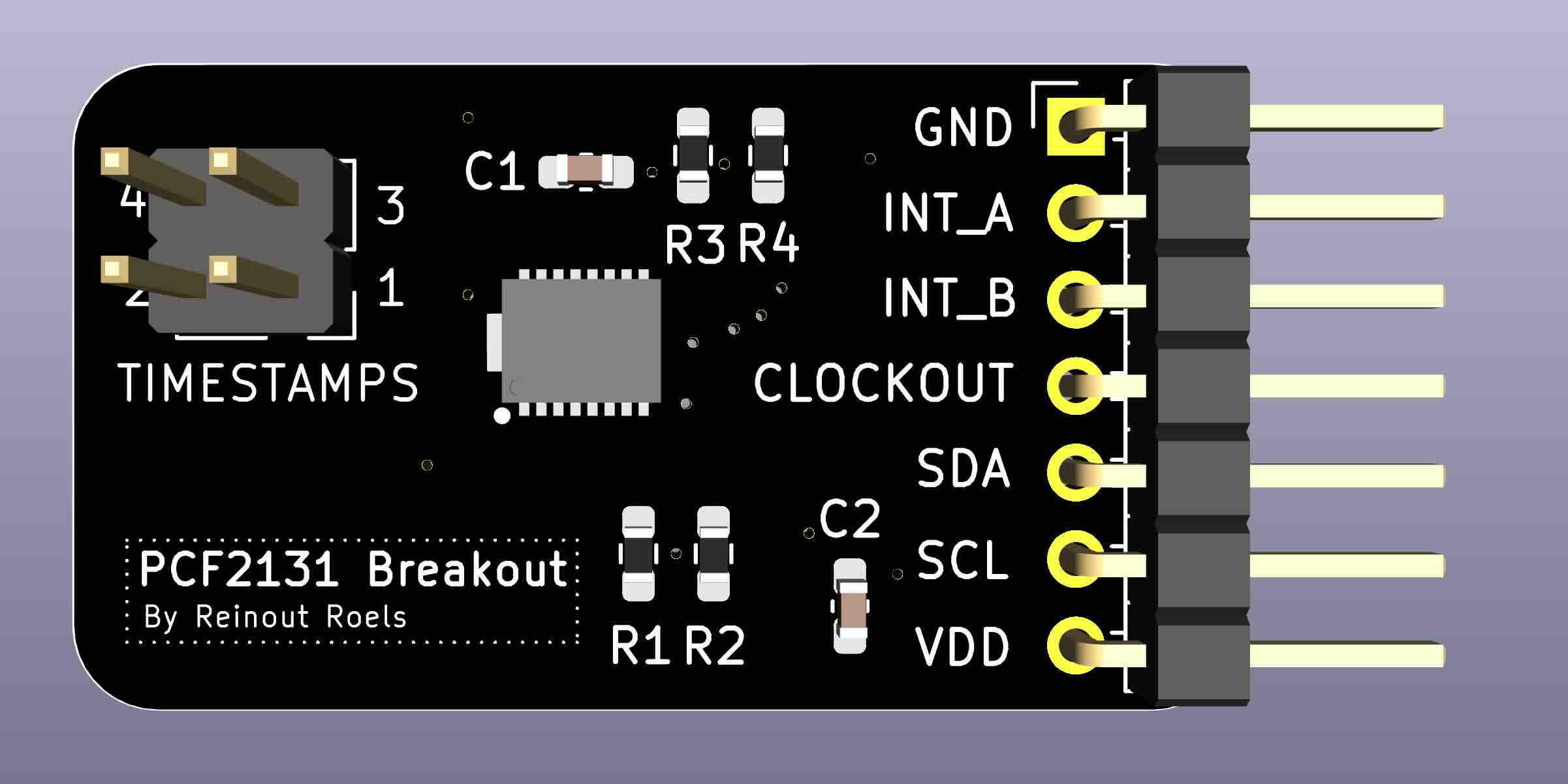
The board has already been manufactured and tested, and I can confirm it works.

However, some design choices have been made that might not meet your needs. For instance, the board is wired for I2C communication only, and there is no support for battery switch-over. Please read section "Design Considerations" for more info on the design choices.

For use with an Arduino, the RTC NXP Arduino library can be used to interface with the chip.

Design Considerations

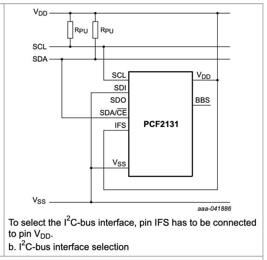
  • Although the PCF2131 supports both I2C and SPI, they require different circuitry, and the choice was made to only support I2C.
  • As expected for a I2C, pull-up resistors are present on the I2C lines.
  • The board was not made to support battery switch-over, and for this reason, it does not have the suggested RC filter circuitry.

Schematics

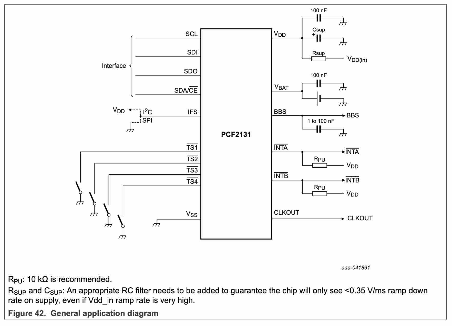
We base ourselves on the following recommended circuits from the datasheet:
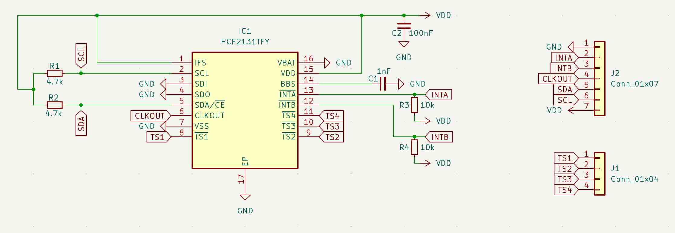
I deliberately left out the RC filter for battery switch-over functionality, which led to the following schematics:
Bill of Materials (BOM)

ReferenceFootprintQtyValue
C1C_0603_1608Metric_Pad1.08x0.95mm_HandSolder11nF
R3,R4R_0603_1608Metric_Pad0.98x0.95mm_HandSolder210k
J1PinHeader_2x02_P2.54mm_Vertical1Conn_01x04
R2,R1R_0603_1608Metric_Pad0.98x0.95mm_HandSolder24.7k
C2C_0603_1608Metric_Pad1.08x0.95mm_HandSolder1100nF
IC1SON50P350X450X150-17N-D1PCF2131TFY
J2PinHeader_1x07_P2.54mm_Horizontal1Conn_01x07

See image of the PCB below to have a better idea of what these components look like.

All capacitors and resistors and SMD 0603. Instead of the horizontal pin header I used, a vertical pin header will also work fine (as long as the pitch is 2.54mm).

How to Obtain the Physical PCB

The Gerber file is in this repository (gerber/PCF2131-breakout.zip). Simply upload this file a PCB manufacturer of your choice (JLPCB, PCBWay, ...), and you they will make it for you for as low as $5 for 5 pieces (with the cheapest shipping option, which can take a few weeks).

[!WARNING] Note that you will still have to solder the components onto the PCB yourself!

How to Edit Design

Everything you need to edit this design in KiCad 8 is included in the repository.

However, this project uses symbols, footprints and 3D models from Component Search Engine. Their license allows us to do pretty much whatever we want with them, except redistributing them. For this reason I can't include them in this repository.

If you would like to edit the design yourself, you will need to download the following component libraries from https://componentsearchengine.com/ (it's free!):

From the downloaded zip file, move the content of the KiCad and 3D subfolders into the project structure, so that the end-result looks like this:
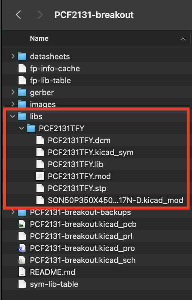
The KiCad project is configured to look for these files in these locations, using relative paths, so no changes to the project itself are required.

Related Sources

Parts

9
QtyValueFootprintReferences
210kResistor_SMD:R_0603_1608Metric_Pad0.98x0.95mm_HandSolderR3, R4
24.7kResistor_SMD:R_0603_1608Metric_Pad0.98x0.95mm_HandSolderR1, R2
1100nFCapacitor_SMD:C_0603_1608Metric_Pad1.08x0.95mm_HandSolderC2
11nFCapacitor_SMD:C_0603_1608Metric_Pad1.08x0.95mm_HandSolderC1
1Conn_01x04Connector_PinHeader_2.54mm:PinHeader_2x02_P2.54mm_VerticalJ1
1Conn_01x07Connector_PinHeader_2.54mm:PinHeader_1x07_P2.54mm_HorizontalJ2
1PCF2131TFYPCF2131TFY:SON50P350X450X150-17N-DIC1

Similar boards

  • 4 layers62 × 105 mmPT100 Datalogger, the printed circuit board in 3D

    PT100 Datalogger

    rasusmilch/PT100_Mesh_Datalogger

    This application turns an ESP32-S3 N8R2 into a UTC-centric PT100 data logger with FRAM-first buffering, SD-card CSV batching/verification, DS3231 RTC support, mesh streaming, and serial-console calibration.

    139 parts
  • 4 layers90 × 60 mmBetter lamp controller, the printed circuit board in 3D

    Better lamp controller

    super-cow-powers/better-lamp-controller

    A custom lamp controller with audio, controlled with an RP2040

    103 partsBSD-3-Clause
  • 2 layers103 × 30.5 mmTS Back Endcap, the printed circuit board in 3D

    TS Back Endcap

    EEVengers/ThunderScope

    ThunderScope GitHub Repo

    9 parts1.3kMIT
  • 2 layers31.8 × 47.6 mmNGC 38 connector, the printed circuit board in 3D

    NGC 38 connector

    rusefi/rusefi

    rusefi - GPL internal combustion engine control unit

    9 parts1.2k
  • 2 layers24 × 27.3 mmExpansion Card Retrofit, the printed circuit board in 3D

    Expansion Card Retrofit

    FrameworkComputer/ExpansionCards

    Reference designs and documentation to create Expansion Cards for the Framework Laptop

    9 parts1.1kCC-BY-4.0
  • 2 layers15.6 × 17.3 mmSKR Mini TFT Thermistor Board, the printed circuit board in 3D

    SKR Mini TFT Thermistor Board

    VoronDesign/Voron-Hardware

    Cool Hardware designed by the Voron Design group

    9 parts1.1kGPL-3.0
  • 2 layers39.1 × 49.5 mmLearnoliver, the printed circuit board in 3D

    Learnoliver

    hackclub/OnBoard

    💡 Join 1,000 teenagers and make your first PCB with a $100 grant!

    9 parts915
  • 2 layers17.4 × 16.9 mmToolhead, the printed circuit board in 3D

    Toolhead

    tanaes/whopping_Voron_mods

    9 parts787GPL-3.0

Questions

How big is the PCF2131-breakout PCB?

It measures 34.2 × 19 mm and has 2 copper layers, 1.6 mm thick.

What parts does the PCF2131-breakout use?

9 parts, built around the PCF2131TFY. The full list of its parts is on this page, with links to each part's symbol and footprint where PCBKit's library has them.

Where can I download the PCF2131-breakout KiCad files?

From the rroels/PCF2131-breakout repository on GitHub, at the commit this page was made from: the board is PCF2131-breakout.kicad_pcb and its schematic PCF2131-breakout.kicad_sch. PCBKit opens the board in the browser, with nothing to install.

Can I use the PCF2131-breakout design in my own project?

Its repository states no licence, so its author keeps all rights: ask rroels before reusing the design.