2 layers69 × 58 mm

 Rr42/USB-C-DB1
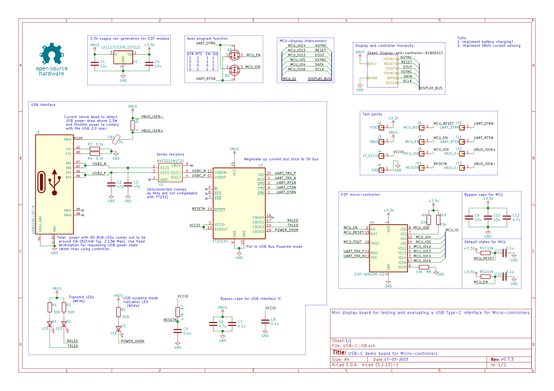
Demo board for testing and evaluating the USB-C interface for Micro-controllers with onboard battery charging.
USB C DB is an open-source printed circuit board by Rr42, from the Rr42/USB-C-DB repository on GitHub, published under the MIT licence. It is a 4-layer board of 85.6 × 54 mm with 202 parts on 135 nets, routed with 2,382 tracks and 336 vias.
It is built around the ESP-WROOM-02, FT231XS-R and 74HC595, with the NA555D, XP262N7002TR-G and 1N4148W among its other parts. Its parts include 87 diodes, 46 resistors, 29 capacitors, 14 connectors and 10 ICs. It belongs with the lEDs and displays and power boards of this library.


This is a mini display board with a USB Type-C connector (carrying USB 2.0) and an onboard micro-controller.
The goal of this display board is to test and evaluate:
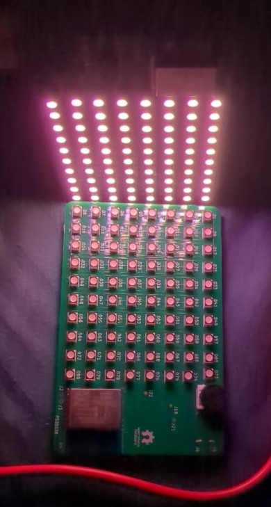
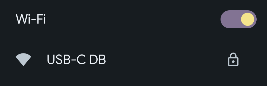
To connect to the display board, simply connect it to power and connect to the WiFi network USB-C DB it hosts.
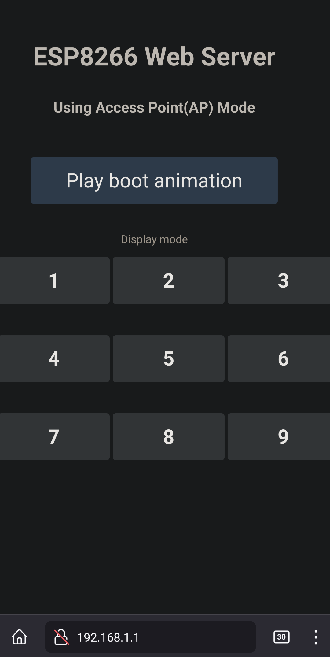
Once connected navigate to http://192.168.1.1 and click/press Play boot animation.
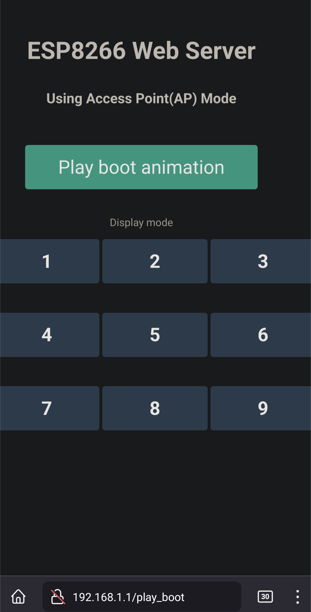
Once the boot animation plays the page will reload with all the functions enabled.
The USB-C display board consumes anywhere from 450mW to a maximum of 800mW depending on the brightness level from 5V USB.
Note that the display board does not have the capability and will not negotiate to any of the higher voltage levels offered by USB PD
For context a 500mAh battery will be able to power the display board for about 3.5 hours (with maximum power level of 800mW) and about 5.5 hours (at the lower 450mW power level).

The Software and firmware of this project is licensed under the the MIT license and the hardware is under the Open Source Hardware license.
| Qty | Value | Footprint | References |
|---|---|---|---|
| 80 | LED_ARGB | LED_SMD:LED_Cree-PLCC4_3.2x2.8mm_CCW | D10, D11, D12, D13, D14, D15, D16, D17, D18, D19, D20, D21, D22, D23, D24, D25 +64 |
| 20 | 583 | Resistor_SMD:R_0603_1608Metric_Pad0.98x0.95mm_HandSolder | R13, R14, R16, R17, R19, R20, R22, R23, R25, R26, R28, R29, R31, R32, R34, R35 +4 |
| 15 | 309 | Resistor_SMD:R_0603_1608Metric_Pad0.98x0.95mm_HandSolder | R1, R2, R5, R15, R18, R21, R24, R27, R30, R33, R36, R39, R42, R43, R44 |
| 11 | 0.1u | Capacitor_SMD:C_0805_2012Metric_Pad1.18x1.45mm_HandSolder | C5, C7, C8, C11, C12, C15, C17, C19, C21, C23, C29 |
| 10 | XP262N7002TR-G | Package_TO_SOT_SMD:SOT-23 | Q1, Q2, Q3, Q4, Q5, Q6, Q7, Q8, Q9, Q10 |
| 7 | 10k | Resistor_SMD:R_0603_1608Metric_Pad0.98x0.95mm_HandSolder | R8, R9, R10, R11, R12, R45, R46 |
| 7 | 47p | Capacitor_SMD:C_0402_1005Metric_Pad0.74x0.62mm_HandSolder | C2, C3, C24, C25, C26, C27, C28 |
| 5 | 1u | Capacitor_SMD:C_0805_2012Metric_Pad1.18x1.45mm_HandSolder | C14, C16, C18, C20, C22 |
| 5 | LED | LED_SMD:LED_Cree-PLCC4_3.2x2.8mm_CCW | D1, D2, D3, D84, D85 |
| 4 | 10u | Capacitor_SMD:C_0805_2012Metric_Pad1.18x1.45mm_HandSolder | C1, C4, C9, C10 |
| 4 | 74HC595 | Package_SO:TSSOP-16_4.4x5mm_P0.65mm | U6, U7, U8, U9 |
| 2 | 1N4148W | Diode_SMD:D_SOD-123 | D86, D87 |
| 2 | 4.7u | Capacitor_SMD:C_0805_2012Metric_Pad1.18x1.45mm_HandSolder | C6, C13 |
| 2 | 5.1k | Resistor_SMD:R_0805_2012Metric_Pad1.20x1.40mm_HandSolder | R3, R4 |
| 1 | 1 | Resistor_SMD:R_0603_1608Metric_Pad0.98x0.95mm_HandSolder | R6 |
| 1 | 3352T-1-105LF | Mouser-imports:3352T1103LF | VR1 |
| 1 | 3u | Resistor_SMD:R_0603_1608Metric_Pad0.98x0.95mm_HandSolder | FB1 |
| 1 | 4.7k | Resistor_SMD:R_0805_2012Metric_Pad1.20x1.40mm_HandSolder | R7 |
| 1 | 74HC595_mod | Package_SO:TSSOP-16_4.4x5mm_P0.65mm | U5 |
| 1 | ESP-WROOM-02 | RF_Module:ESP-WROOM-02 | U4 |
| 1 | FT231XS | Package_SO:SSOP-20_3.9x8.7mm_P0.635mm | U3 |
| 1 | FT_VCCIO | TestPoint:TestPoint_Pad_D1.0mm | J4 |
| 1 | GND | TestPoint:TestPoint_Pad_D1.0mm | J5 |
| 1 | IBUS_S+ | TestPoint:TestPoint_Pad_D1.0mm | J12 |
| 1 | IBUS_S- | TestPoint:TestPoint_Pad_D1.0mm | J13 |
| 1 | LD1117S33TR_SOT223 | Package_TO_SOT_SMD:SOT-223-3_TabPin2 | U1 |
| 1 | LOGO | USB-C-DB:oshw-spfmb | G1 |
| 1 | MCU_EN | TestPoint:TestPoint_Pad_D1.0mm | J7 |
| 1 | MCU_IO0 | TestPoint:TestPoint_Pad_D1.0mm | J9 |
| 1 | MCU_RST | TestPoint:TestPoint_Pad_D1.0mm | J6 |
| 1 | NA555D | Package_SO:SOIC-8_3.9x4.9mm_P1.27mm | U10 |
| 1 | NUF2221W1T2G | Mouser-imports:SOT65P210X110-6N | U2 |
| 1 | P3V3 | TestPoint:TestPoint_Pad_D1.0mm | J2 |
| 1 | PWM_BC | TestPoint:TestPoint_Pad_D1.0mm | J16 |
| 1 | RESETN | TestPoint:TestPoint_Pad_D1.0mm | J14 |
| 1 | UART_DTRN | TestPoint:TestPoint_Pad_D1.0mm | J10 |
| 1 | UART_RTSN | TestPoint:TestPoint_Pad_D1.0mm | J11 |
| 1 | USB4105-GF-A | SnapEDA-imports:GCT_USB4105-GF-A | J1 |
| 1 | VBUS | TestPoint:TestPoint_Pad_D1.0mm | J3 |
The 199 most common of 202 parts.
It measures 85.6 × 54 mm and has 4 copper layers, 1.6 mm thick.
202 parts, built around the ESP-WROOM-02, FT231XS-R, 74HC595 and NA555D. The full list of its parts is on this page, with links to each part's symbol and footprint where PCBKit's library has them.
From the Rr42/USB-C-DB repository on GitHub, at the commit this page was made from: the board is Hardware/USB-C-DB/USB-C-DB.kicad_pcb. PCBKit opens the board in the browser, with nothing to install.
Its repository publishes it under the MIT licence: you may reuse it on that licence's terms (keep the author's notice, and for a copyleft licence share your changes alike).


nsm81/VehicleJunctionBox_PCBs
The junction box is an intermediate stage between the accumulator and inverter. It contains an HVD, a current sensor, discharge circuitry, TSAL and TSMPs.


jibonaronno/documentsA
It is required to change settings using SCLManager.exe when required for new setup.