2 layers30 × 61.3 mm

 roro297/compressorpedal
This project designs and documents an analog guitar compressor: input/output adaptation, amplification, envelope detection, and gain control. It includes the schematic, PCB, as well as simulations and test results.
PedaleGuitareComp is an open-source printed circuit board by roro297, from the roro297/compressorpedal repository on GitHub. It is a 2-layer board of 80 × 85 mm with 47 parts on 30 nets, routed with 272 tracks and 11 vias.
Its parts include 20 resistors, 8 capacitors, 5 transistors, 3 connectors and 2 switches.
Complete analog guitar compressor pedal project, including schematic and PCB design (KiCad) and simulations (LTSpice).
This project designs and documents an analog guitar compressor: input/output adaptation, amplification, envelope detection, and gain control. It includes the schematic, PCB, as well as simulations and test results.
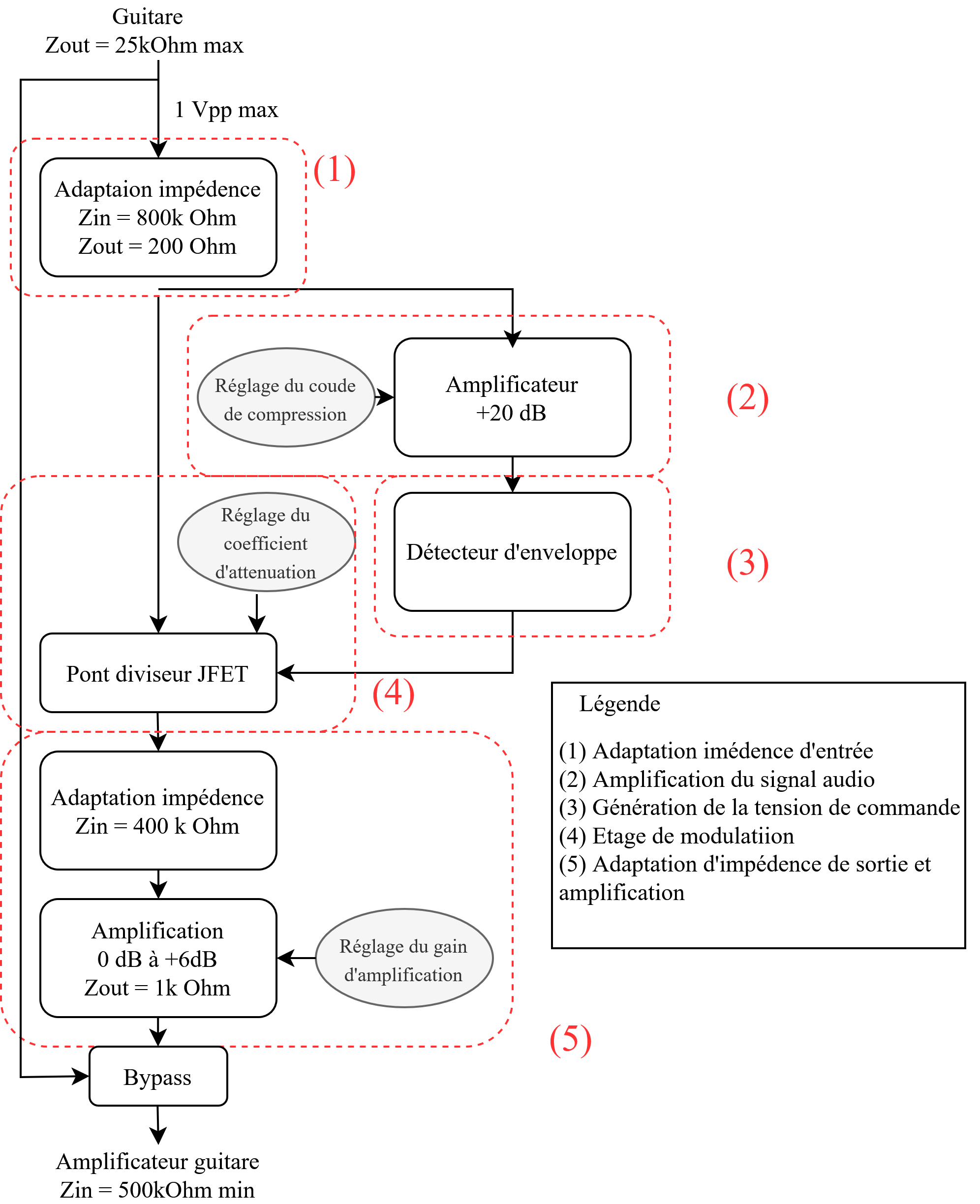
Global diagram — Functional architecture of the pedal
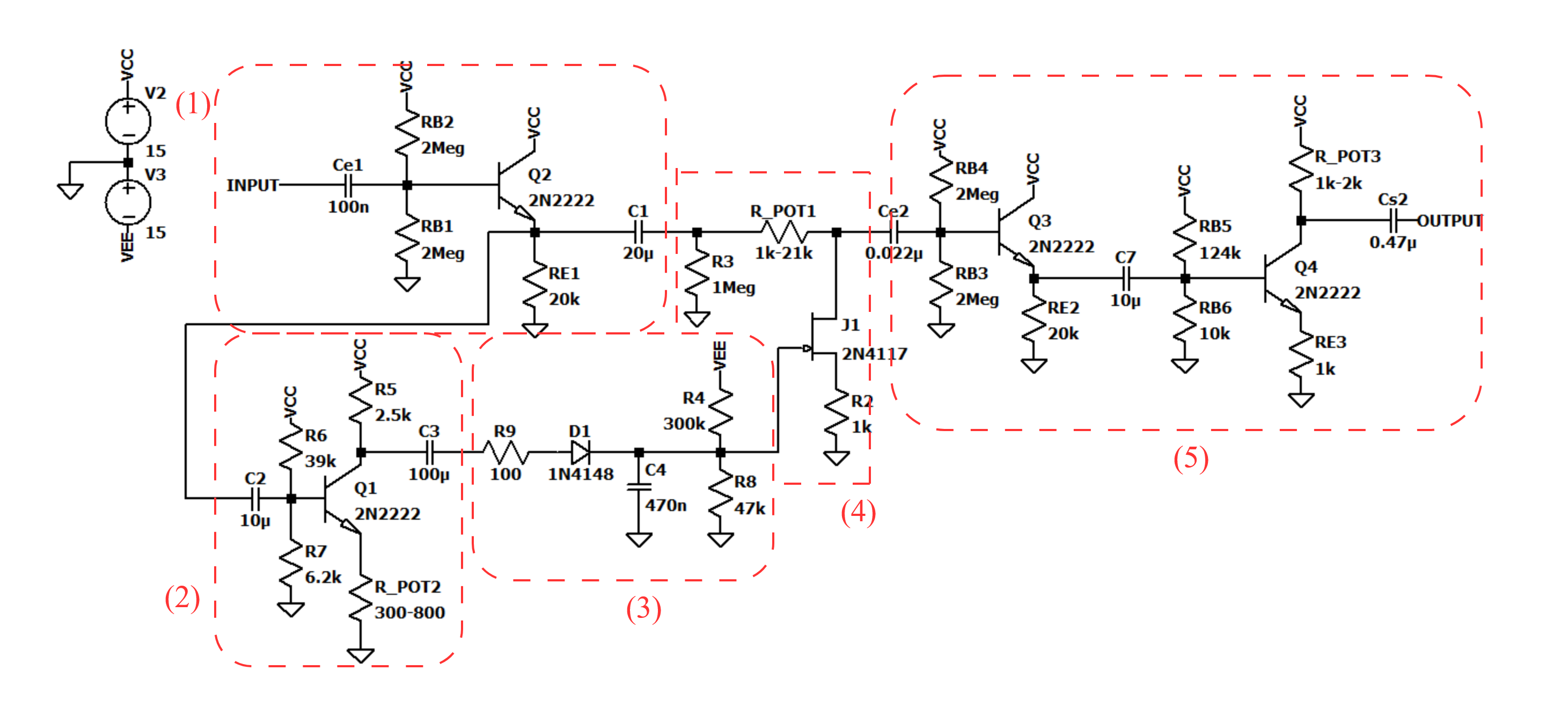
Global circuit — Schematic overview
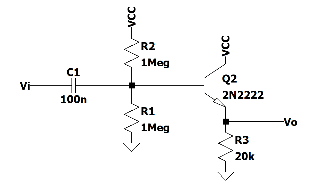
Input adaptation — Guitar signal conditioning
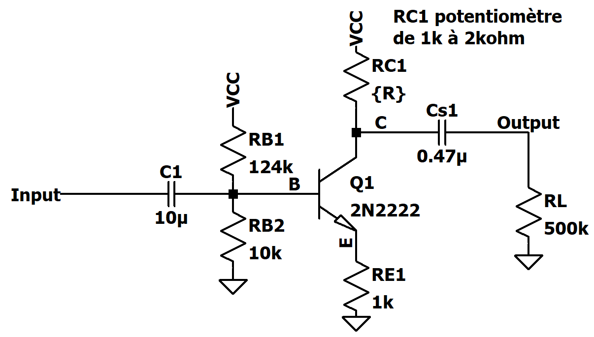
Amplification — Signal amplification stages
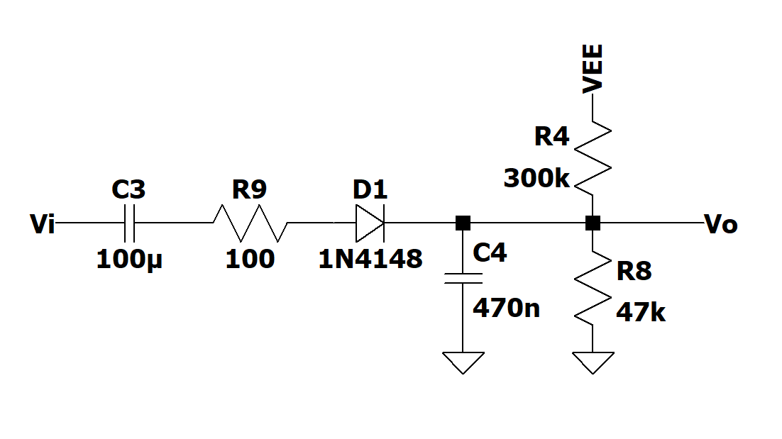
Peak detection — Envelope generation for control
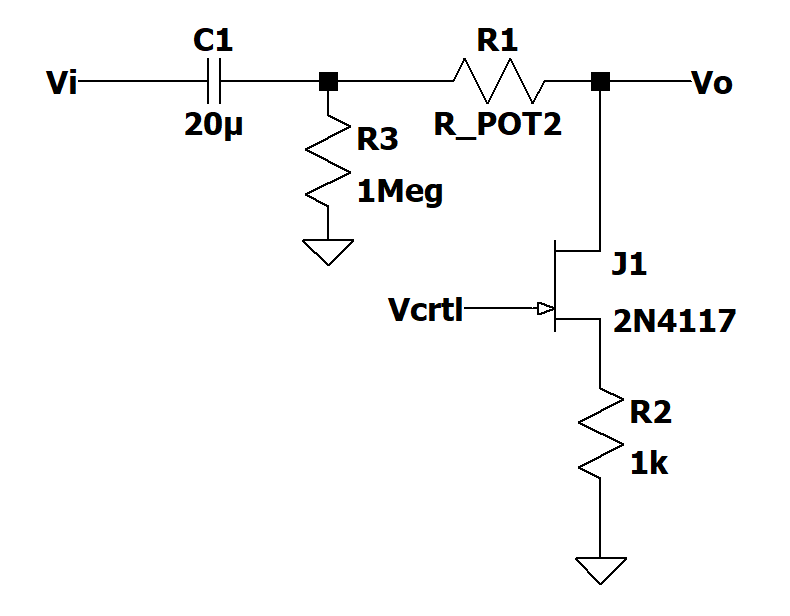
Gain control — Envelope‑controlled attenuation
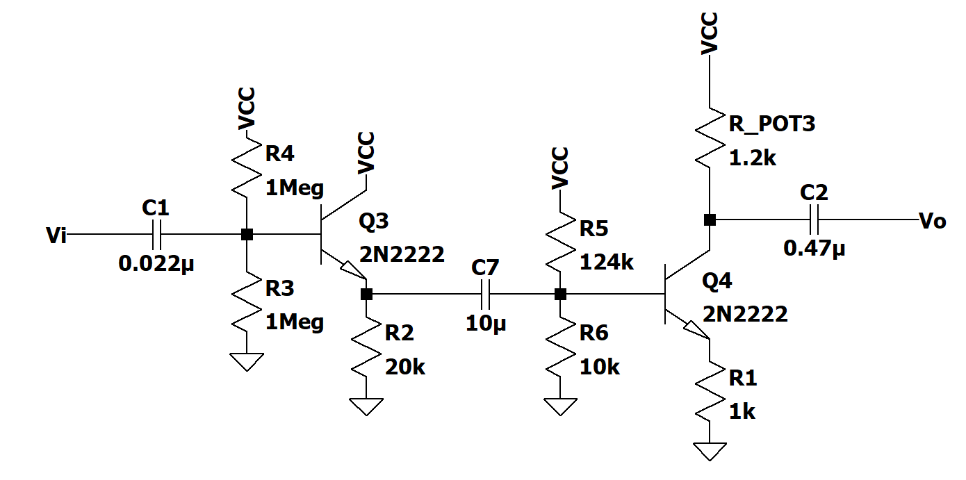
Output adaptation — Compatibility with amp or audio interface
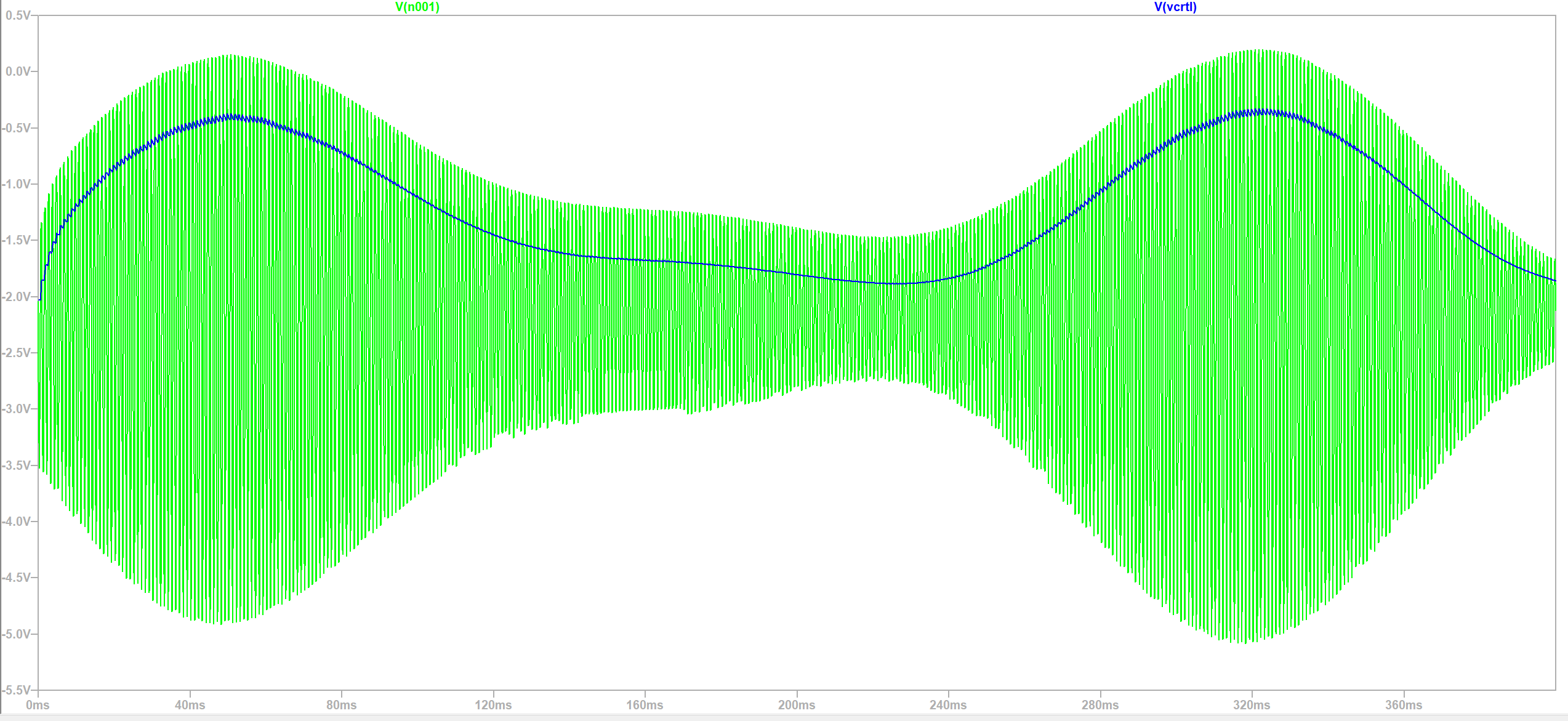
Envelope simulation — Detection response
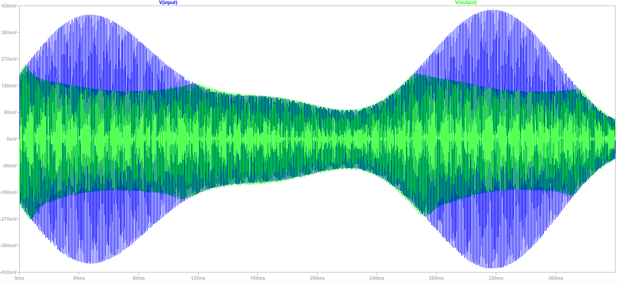
Signal simulation — Compression effect on the signal
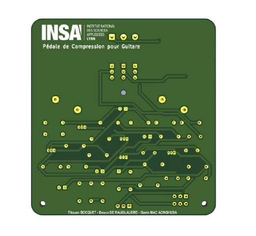
PCB back side
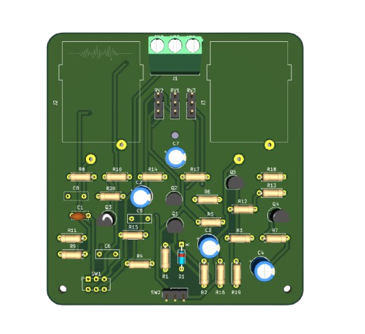
PCB component side
Analog-Compressor-Pedal/
├── README.md
├── doc/                       # Visual documentation and images
├── LTSpice/                   # Schematics and simulation tests
│   ├── Circuit_complet_avec_Adaptation.asc
│   ├── Audio Tests/
│   ├── Circuit Test Results/
│   └── PWL Sound Files/
└── pedaleGuitareComp/         # KiCad project (schematic + PCB)
		├── pedaleGuitareComp.kicad_sch
		├── pedaleGuitareComp.kicad_pcb
└── footprints_perso/| Qty | Value | Footprint | References |
|---|---|---|---|
| 4 | 1k | Resistor_THT:R_Axial_DIN0207_L6.3mm_D2.5mm_P7.62mm_Horizontal | R9, R10, R19, R20 |
| 4 | 2N2222 | Package_TO_SOT_THT:TO-92_Inline | Q1, Q2, Q4, Q5 |
| 3 | 1M | Resistor_THT:R_Axial_DIN0207_L6.3mm_D2.5mm_P7.62mm_Horizontal | R4, R12, R13 |
| 2 | 10u | Capacitor_THT:CP_Radial_D6.3mm_P2.50mm | C3, C7 |
| 2 | 20k | Resistor_THT:R_Axial_DIN0207_L6.3mm_D2.5mm_P7.62mm_Horizontal | R3, R14 |
| 2 | 2M | Resistor_THT:R_Axial_DIN0207_L6.3mm_D2.5mm_P7.62mm_Horizontal | R1, R2 |
| 1 | clipboard:127030a1-c690-4418-a720-fd34b482877e | ||
| 1 | clipboard:5e10ae1c-495f-4db6-8730-ded183f1f888 | ||
| 1 | 0.022u | Capacitor_THT:C_Rect_L7.2mm_W2.5mm_P5.00mm | C5 |
| 1 | 0.47u | Capacitor_THT:C_Rect_L7.2mm_W2.5mm_P5.00mm | C8 |
| 1 | 100 | Resistor_THT:R_Axial_DIN0207_L6.3mm_D2.5mm_P7.62mm_Horizontal | R11 |
| 1 | 100n | Capacitor_THT:C_Disc_D5.0mm_W2.5mm_P5.00mm | C1 |
| 1 | 100u | Capacitor_THT:CP_Radial_D6.3mm_P2.50mm | C4 |
| 1 | 10k | Resistor_THT:R_Axial_DIN0207_L6.3mm_D2.5mm_P7.62mm_Horizontal | R18 |
| 1 | 124k | Resistor_THT:R_Axial_DIN0207_L6.3mm_D2.5mm_P7.62mm_Horizontal | R17 |
| 1 | 1N4148 | Diode_THT:D_DO-35_SOD27_P7.62mm_Horizontal | D1 |
| 1 | 2.5k | Resistor_THT:R_Axial_DIN0207_L6.3mm_D2.5mm_P7.62mm_Horizontal | R7 |
| 1 | 20u | Capacitor_THT:CP_Radial_D6.3mm_P2.50mm | C2 |
| 1 | 2N4117 | Package_TO_SOT_THT:TO-92_Inline | Q3 |
| 1 | 300 | Resistor_THT:R_Axial_DIN0207_L6.3mm_D2.5mm_P7.62mm_Horizontal | R8 |
| 1 | 300k | Resistor_THT:R_Axial_DIN0207_L6.3mm_D2.5mm_P7.62mm_Horizontal | R15 |
| 1 | 39k | Resistor_THT:R_Axial_DIN0207_L6.3mm_D2.5mm_P7.62mm_Horizontal | R5 |
| 1 | 470n | Capacitor_THT:C_Rect_L7.2mm_W2.5mm_P5.00mm | C6 |
| 1 | 47k | Resistor_THT:R_Axial_DIN0207_L6.3mm_D2.5mm_P7.62mm_Horizontal | R16 |
| 1 | 6.2k | Resistor_THT:R_Axial_DIN0207_L6.3mm_D2.5mm_P7.62mm_Horizontal | R6 |
| 1 | AudioJack-Guitare-INPUT | Connector_Audio:Jack_speakON-6.35mm_Neutrik_NLJ2MDXX-H_Horizontal | J3 |
| 1 | AudioJack-Guitare-OUTPUT | Connector_Audio:Jack_speakON-6.35mm_Neutrik_NLJ2MDXX-H_Horizontal | J2 |
| 1 | DIN-ALIM | TerminalBlock_Phoenix:TerminalBlock_Phoenix_MKDS-1,5-3_1x03_P5.00mm_Horizontal | J1 |
| 1 | EFECT-CHOICE | Connector_PinHeader_2.54mm:PinHeader_1x03_P2.54mm_Vertical | SW2 |
| 1 | R_Amp (1 kOhm) | Connector_PinHeader_2.54mm:PinHeader_1x03_P2.54mm_Vertical | RV3 |
| 1 | R_Amp_Tot (20 kOhm) | Connector_PinHeader_2.54mm:PinHeader_1x03_P2.54mm_Vertical | RV1 |
| 1 | R_Comp (500 Ohm) | Connector_PinHeader_2.54mm:PinHeader_1x03_P2.54mm_Vertical | RV2 |
| 1 | SW_ALIM | Button_Switch_THT:SW_E-Switch_EG1271_SPDT | SW1 |
The 44 most common of 47 parts.
It measures 80 × 85 mm and has 2 copper layers, 1.6 mm thick.
47 parts. The full list of its parts is on this page, with links to each part's symbol and footprint where PCBKit's library has them.
From the roro297/compressorpedal repository on GitHub, at the commit this page was made from: the board is pedaleGuitareComp/pedaleGuitareComp.kicad_pcb and its schematic pedaleGuitareComp/pedaleGuitareComp.kicad_sch. PCBKit opens the board in the browser, with nothing to install.
Its repository states no licence, so its author keeps all rights: ask roro297 before reusing the design.


VoronDesign/Voron-Hardware
Cool Hardware designed by the Voron Design group

hackclub/OnBoard
💡 Join 1,000 teenagers and make your first PCB with a $100 grant!


FrameworkComputer/InputModules
Reference designs and documentation for the Input Module system in the Framework Laptop 16