
4 layers350 × 155 mm
Ventilator
RespiraWorks/Ventilator
Fully-featured ICU ventilator design, optimized for manufacture using commonly available components and free to license.
788 parts169Apache-2.0

 lhndo/LH-Stinger1.1k
Fast, Precise, Cartesian, FDM 3D Printer
LHS Breakbeat is an open-source printed circuit board by lhndo, from the lhndo/LH-Stinger repository on GitHub. It is a 2-layer board of 114 × 61.4 mm with 47 parts on 57 nets, routed with 463 tracks and 2 vias.
It is built around the BAT54J. Its parts include 25 connectors, 3 diodes, 2 resistors and 2 fuses. It belongs with the robots and motor control boards of this library.
Disclaimer
This is a DIY (Do-It-Yourself) experimental project. This PCB is provided "as is" without any guarantees or warranty, and is not certified for any commercial or critical applications. Use it at your own risk. The creator assumes no liability for damages or injuries resulting from its use, including but not limited to fire, electric shock, personal injury or property damage. By using this PCB, you agree to the terms of this disclaimer.
NOTE: this design is currently in testing
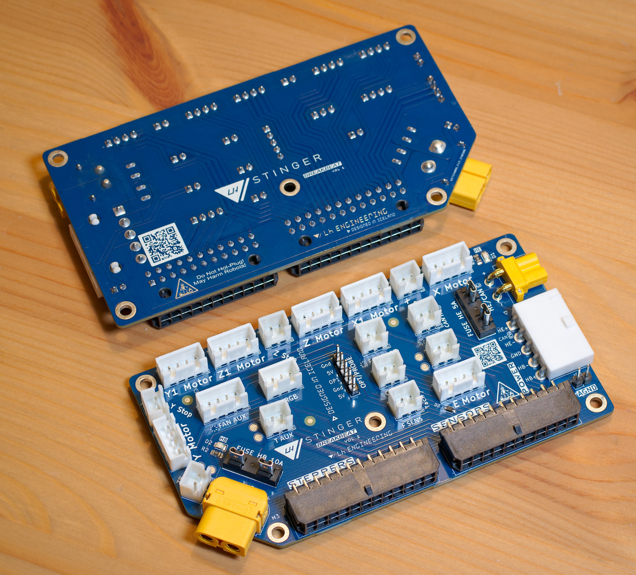
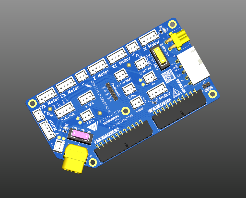
LHS Breakbeat is a breakout board built for the LH Stinger, meant to provide an easy interface between the external electronics box and the printer electronics.
This board is meant to be mounted on the printer, and make most of the wiring setup plug and play.
Note: these guideline limits are on top of your mainboard specifications, along with the wires and connectors used for the wire harness.
| Circuit | Limit |
|---|---|
| Hotend Heater | 24V, 115W, 4.8 A |
| Bed Heater | 24V, 220W, 9.2 A |
| Fans | 24V, 2 A |
| RGB/5V | 2A |
| Steppers | 2.7 A |
Please see the Interactive BOM
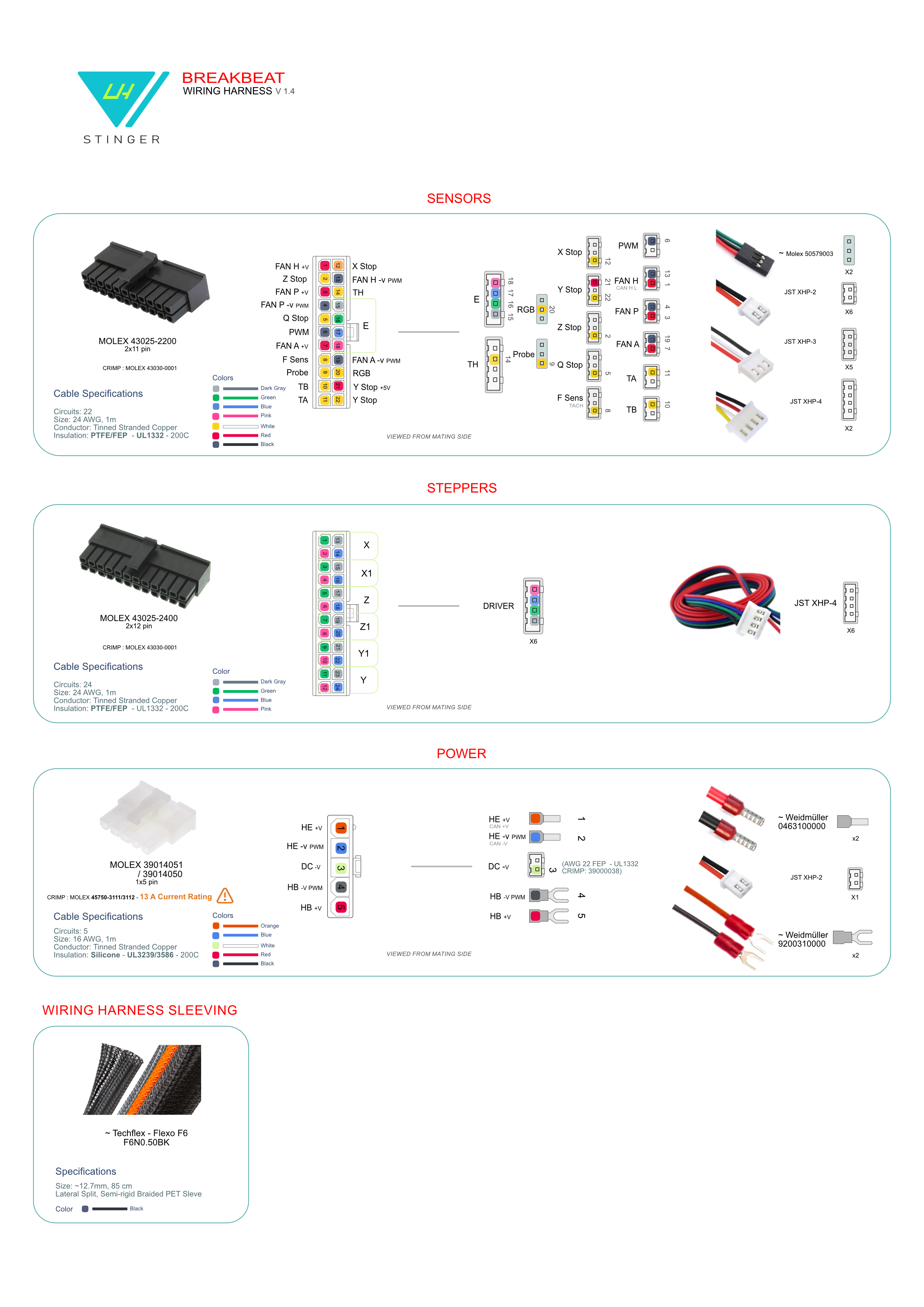
https://github.com/lhndo/LH-Stinger/wiki/Breakout-Box
Thanks to @roerich_64 and the LHS community for the help and guidance with this project!
| Qty | Value | Footprint | References |
|---|---|---|---|
| 5 | Mounting Hole M3 | MountingHole:MountingHole_3.2mm_M3_DIN965_Pad | H1, H2, H3, H4, H5 |
| 3 | Fiducial | Fiducial:Fiducial_1.5mm_Mask3mm | FID1, FID2, FID3 |
| 2 | 4.7K | Resistor_SMD:R_0805_2012Metric_Pad1.20x1.40mm_HandSolder | R1, R2 |
| 2 | Green | LED_SMD:LED_0805_2012Metric_Pad1.15x1.40mm_HandSolder | D1, D2 |
| 2 | Test TA | TestPoint:TestPoint_Pad_D2.0mm | TP3, TP4 |
| 2 | Test TB | TestPoint:TestPoint_Pad_D2.0mm | TP5, TP6 |
| 2 | Test TH | TestPoint:TestPoint_Pad_D2.0mm | TP1, TP2 |
| 1 | AGND In/ GND Jumper | Connector_PinHeader_2.54mm:PinHeader_1x02_P2.54mm_Vertical | JP1 |
| 1 | BAT54J | Diode_SMD:D_SOD-323F | D3 |
| 1 | Endstop Q | Connector_JST:JST_XH_B2B-XH-A_1x02_P2.50mm_Vertical | J25 |
| 1 | Endstop X | Connector_JST:JST_XH_B2B-XH-A_1x02_P2.50mm_Vertical | J12 |
| 1 | Endstop Y | Connector_JST:JST_XH_B2B-XH-A_1x02_P2.50mm_Vertical | J13 |
| 1 | Endstop Z | Connector_JST:JST_XH_B2B-XH-A_1x02_P2.50mm_Vertical | J26 |
| 1 | Fan Aux | Connector_JST:JST_XH_B4B-XH-A_1x04_P2.50mm_Vertical | J14 |
| 1 | Fan Hotend/Can HL | Connector_JST:JST_XH_B2B-XH-A_1x02_P2.50mm_Vertical | J16 |
| 1 | Fan Part | Connector_JST:JST_XH_B2B-XH-A_1x02_P2.50mm_Vertical | J15 |
| 1 | Filament Sensor / Tach | Connector_JST:JST_XH_B2B-XH-A_1x02_P2.50mm_Vertical | J11 |
| 1 | Fuse HB 10A | Library:Fuseholder_Blade_Mini_Keystone_3568 | F2 |
| 1 | Fuse HE 5A | Fuse:Fuseholder_Blade_Mini_Keystone_3568 | F1 |
| 1 | Hotbed | AC:AMASS_XT60PW-F_1x02_P7.20mm_Horizontal | J5 |
| 1 | Hotend / Can 24V | Mouser:XT30PWF | J4 |
| 1 | Motor E | Connector_JST:JST_XH_B4B-XH-A_1x04_P2.50mm_Vertical | J24 |
| 1 | Motor X | Connector_JST:JST_XH_B4B-XH-A_1x04_P2.50mm_Vertical | J17 |
| 1 | Motor X1 | Connector_JST:JST_XH_B4B-XH-A_1x04_P2.50mm_Vertical | J19 |
| 1 | Motor Y | Connector_JST:JST_XH_B4B-XH-A_1x04_P2.50mm_Vertical | J23 |
| 1 | Motor Y1 | Connector_JST:JST_XH_B4B-XH-A_1x04_P2.50mm_Vertical | J22 |
| 1 | Motor Z | Connector_JST:JST_XH_B4B-XH-A_1x04_P2.50mm_Vertical | J20 |
| 1 | Motor Z1 | Connector_JST:JST_XH_B4B-XH-A_1x04_P2.50mm_Vertical | J21 |
| 1 | Power In | Mouser:39303055 | J3 |
| 1 | Probe/Optional Header | Connector_PinHeader_2.54mm:PinHeader_1x05_P2.54mm_Vertical | J27 |
| 1 | RGB | Connector_JST:JST_XH_B3B-XH-A_1x03_P2.50mm_Vertical | J10 |
| 1 | Sensors In | Mouser:43045-22_00,01,02,10_ | J2 |
| 1 | Steppers In | Mouser:0430452400 | J1 |
| 1 | Thermistor Aux | Connector_JST:JST_XH_B2B-XH-A_1x02_P2.50mm_Vertical | J9 |
| 1 | Thermistor Bed | Connector_JST:JST_XH_B2B-XH-A_1x02_P2.50mm_Vertical | J7 |
| 1 | Thermistor HE/Can L | Connector_JST:JST_XH_B2B-XH-A_1x02_P2.50mm_Vertical | J8 |
RespiraWorks/Ventilator
Fully-featured ICU ventilator design, optimized for manufacture using commonly available components and free to license.

fliperama86/neopico-hd
Digital video and audio capture with HDMI output for Neo Geo MVS arcade hardware using Raspberry Pi Pico 2

c0de111/tinta
Battery-powered e-paper sign: room signage, sensor graphs, home automation, or anything over Wi-Fi. Wakes by real-time clock, NFC tap, or button. Raspberry Pi Pico W firmware, custom PCB, and 3D-printed case included.

alpauna/TritonECU
ESP32-S3 engine control unit — fuel injection, ignition timing, wideband O2 (CJ125/LSU 4.9), dashboard, and MQTT telemetry

miameows/E-Fidget
Hi there! There's a lot of moving parts with this project right now, so why don't you check out my latest blog post for more info?

TheEccentricGenius/INK4u_Board
An UNO form factor board with a AVR128DA28 processor.


open-batt/openbms-hardware
OpenBMS - Open Source Battery Management System Hardware
It measures 114 × 61.4 mm and has 2 copper layers, 1.66 mm thick.
47 parts, built around the BAT54J. The full list of its parts is on this page, with links to each part's symbol and footprint where PCBKit's library has them.
From the lhndo/LH-Stinger repository on GitHub, at the commit this page was made from: the board is PCB/LHS Breakbeat/LHS Breakbeat.kicad_pcb and its schematic PCB/LHS Breakbeat/LHS Breakbeat.kicad_sch. PCBKit opens the board in the browser, with nothing to install.
Its repository states no licence, so its author keeps all rights: ask lhndo before reusing the design.