


10 layers70 × 50 mm
Soilsense
wasylews/soilsense
A low-power soil moisture and climate sensor on an ESP-01, powered by a single 18650 cell for an estimated six months. Custom PCB and a 3D-printed enclosure.
29 parts

 RobThree/TemperatureDisplay3
Measures temperature and humidity using a GXHT30 and displays this information on an SSD1306 OLED display. Offers a HTTP endpoint to read values as JSON, also outputs values on serial.
TemperatureDisplay is an open-source printed circuit board by RobThree, from the RobThree/TemperatureDisplay repository on GitHub, published under the MIT licence. It is a 2-layer board of 25.7 × 34.4 mm with 4 parts on 16 nets, routed with 20 tracks and 0 vias.
It is built around the GXHT30. It belongs with the lEDs and displays and interfaces and adapters boards and the ESP8266 boards of this library.
 Temperature Display
Uses an Wemos D1 mini with a GXHT30 I²C temperature & humidity sensor and a SSD1306 I²C 0.96" OLED display.
This project supports OTA updates, uses the WiFi manager to configure the WiFi and provides a REST API to get the temperature and humidity as JSON. The readings (and display) are updated every 2 seconds (by default, configurable) and also output to serial.
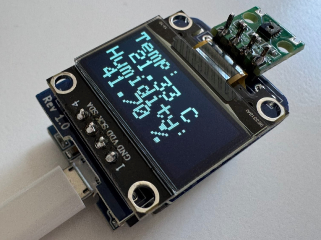
You'll need:
All of these components are readily available at the time of writing, you should be able to easily source them.
The pcb directory contains the KiCad (9.0) design files for the Wemos D1 mini shield PCB. PCBWay reached out to me and was kind enough to support this project. The project is available at PCBWay's Shared Projects for easy ordering.
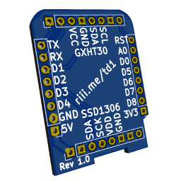

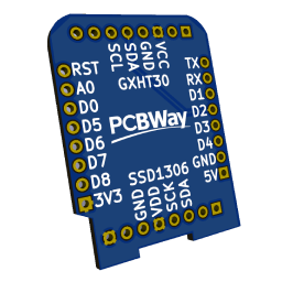


For more pictures of the PCB and/or project see the project page or the /img/PCBWay directory. I would like to thank PCBWay again 🙏 Shipping was incredibly quick 🛫🛬 and the PCB is perfectly finished 👌
In a next iteration I'm hoping to integrate the GXHT30 on the shield, but being pretty new to PCB design this first iteration uses a module.
Connect the GXHT30 and SSD1306 to the Wemos D1 mini's 3v3 pin, connect the grounds of all three modules. And connect SDA to D2 (GPIO4) and SCL to D1 (GPIO5). That's it. Done. Apparently some modules require 5V; if your display is glitching or not turning on, try connecting it to the 5V pin on the Wemos D1 mini. I power the project via the Wemos' onboard USB port but you should also be able to power it by directly powering the power pins.
                           +----------+        +------------------+
                           |  GXHT30  |        |     SSD1306      |
                           |    [X]   |        |                  |
                           |          |        |                  |
                           | V G  S S |        |    V  G  S  S    |
   +-----------------+     | C N  D C |        |    C  N  D  C    |
   |  Wemos D1 mini  |     | C D  A L |        |    C  D  A  K    |
   |    (ESP8266)    |     +----------+        +------------------+
   |                 |       | |  | |               |  |  |  |
   |              D1 |-------|-|--|-+---------------|--|--|--+
   |              D2 |-------|-|--+-----------------|--|--+
   |                 |       | |                    |  |
   |                 |       | |                    |  |
   |                 |       | |                    |  |
   |                 |       | |                    |  |
   |             GND |-------|-+--------------------|--+
+--| 3V3             |       |                      |
|  +-----------------+       |                      |
+----------------------------+----------------------+This is a PlatformIO project. I'm sure someone will help convert this to an Arduino IDE project, but it's not going to be me.
include/example_config.h to include/config.h and change the OTA update password and devicename (this one is optional)example_env_secrets.ini to env_secrets.ini and set the same password for the --auth optionplatformio.ini file has default_envs set to d1_mini_serialdefault_envs set to d1_mini_ota and the correct IP in env_secrets.ini at the upload_port entry), no more need for USB cablesThe display will show the temperature in °C or Fahrenheit (see include/config.h) and the humidity in %RH (Relative Humidity). If your sensor is way off you can fix this by setting TEMPERATUREOFFSET and/or HUMIDITYOFFSET in include/config.h and updating the device or, much easier, by using the web UI. The temperature and humidity will also be output to the serial port every time the sensor is read (see UPDATEINTERVAL) and when you use the /read endpoint of the REST API (e.g. http://<deviceip>/read [GET]) you'll get the readings as json:
{
  "celsius": {
    "temperature": 22.81,
    "offset": -5
  },
  "fahrenheit": {
    "temperature": 73.058,
    "offset": -9
  },
  "humidity": {
    "relative_perc": 31.29,
    "relative_perc_offset": 8
  },
  "wifi": {
    "rssi": -48
  },
  "lastupdate": "1.62 seconds ago",
  "display": "c",
  "devicename": "MyDevice"
}
These values are only updated every time the sensor is read (again: see UPDATEINTERVAL). There is also a /reset endpoint ([PUT]) that will reboot the device.
Finally, the device also offers a user-friendly UI at the / endpoint (e.g. http://<deivce-ip-here>/) which updates every 5 seconds:
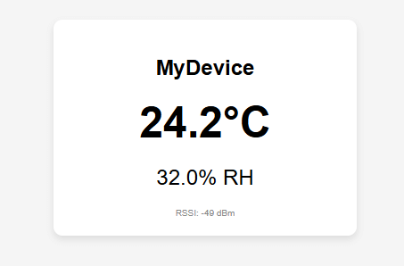
You can find the settings at http://<deivce-ip-here>/settings or by clicking the cog in the top right corner of the home screen. The settings screen allows you to adjust some values. Once your changed settings have been saved you can go back home by clicking the 'home' icon in the top right corner.
| Qty | Value | Footprint | References |
|---|---|---|---|
| 2 | Connector_Generic:Conn_01x08 | Connector_PinHeader_2.54mm:PinHeader_1x08_P2.54mm_Vertical | P1, P2 |
| 1 | GXHT30 | Connector_PinHeader_2.54mm:PinHeader_1x08_P2.54mm_Vertical | J2 |
| 1 | SSD1306 | Connector_PinHeader_2.54mm:PinHeader_1x08_P2.54mm_Vertical | J1 |
It measures 25.7 × 34.4 mm and has 2 copper layers, 1.6 mm thick.
4 parts, built around the GXHT30. The full list of its parts is on this page, with links to each part's symbol and footprint where PCBKit's library has them.
From the RobThree/TemperatureDisplay repository on GitHub, at the commit this page was made from: the board is pcb/Temperature Display.kicad_pcb and its schematic pcb/Temperature Display.kicad_sch. PCBKit opens the board in the browser, with nothing to install.
Its repository publishes it under the MIT licence: you may reuse it on that licence's terms (keep the author's notice, and for a copyleft licence share your changes alike).
wasylews/soilsense
A low-power soil moisture and climate sensor on an ESP-01, powered by a single 18650 cell for an estimated six months. Custom PCB and a 3D-printed enclosure.

joypad-ai/joypad-os
Universal controller firmware for building adapters, dongles, and custom controllers.


hackclub/OnBoard
💡 Join 1,000 teenagers and make your first PCB with a $100 grant!

tardate/LittleArduinoProjects
a collection of "Little Electronic & Arduino Projects", most involving electronics or an Arduino in one way or another!

drandyhaas/KiCadRoutingTools
A set of Python/Rust tools to aid routing in KiCad

osy/XG_Mobile_Station
Open source eGPU dock for ROG Ally and ROG Flow

Luos-io/luos_engine
Open-source and real-time orchestrator for cyber-physical-systems, to easily design, test and deploy embedded applications and digital twins.