2 layers103 × 30.5 mm
 RobThree/OpenSpool-AMS3
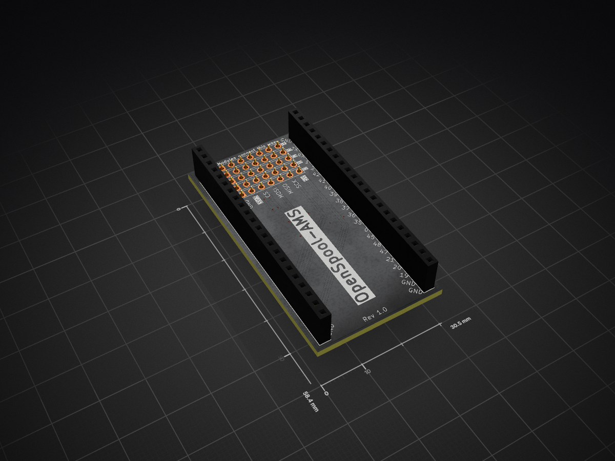
A PCB to connect up to 5 PN532 NFC reader modules to an ESP32 S3 WROOM devkit board
OpenSpool AMS is an open-source printed circuit board by RobThree, from the RobThree/OpenSpool-AMS repository on GitHub, published under the MIT licence. It is a 2-layer board of 30.5 × 58.4 mm with 9 parts on 40 nets, routed with 75 tracks and 11 vias.
It belongs with the radio and wireless boards and the ESP32 boards of this library.
This repository contains the PCB design for the OpenSpool project. This PCB can connect up to 5 PN532 NFC reader modules to an ESP32 S3 WROOM devkit board.
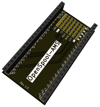
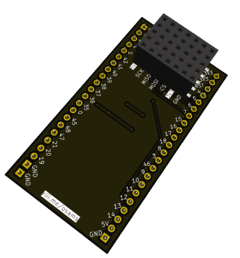
You can use this board on top, or on the bottom of your ESP32. Depending on which side you solder the female (or male) sockets (or pinheaders) you can then use the other side to connect your NFC readers to. The pins are in the same order as the pins on the PN532 board so you should be able to use dupont wires 6-wide (without tearing the wires apart). The wires should then go straight from this board to the PN532 module.
Note that the 'connectorblock' has an extra row of pins for 5 volts. You don't need to populate this. However, if for some reason your PN532 readers won't work you can try connecting the 3V3 wire to this 5V rail. Some PN532 reader modules apparently won't work on 3V3 (I haven't encountered them yet).
1x ESP32 S3 WROOM DEVKIT2x 22 pin female pin socket or pin header6x 5 pin female pin socket or pin header (+1 if you want to populate the 5V one whilst also populating the 3V3 one)1x per PN532 reader 6 pin wide dupont wire male/female as you see fit0 through 4) and pay extra close attention the the 3V3 and 5V pins to ensure the correct ones go to VCC on the PN532 module.For more instructions, or how to proceed after this, see the OpenSpool project.
| Qty | Value | Footprint | References |
|---|---|---|---|
| 1 | 3V3 | Connector_PinSocket_2.54mm:PinSocket_1x05_P2.54mm_Vertical | J7 |
| 1 | 5V | Connector_PinSocket_2.54mm:PinSocket_1x05_P2.54mm_Vertical | J4 |
| 1 | CS | Connector_PinSocket_2.54mm:PinSocket_1x05_P2.54mm_Vertical | J6 |
| 1 | ESP32-L | Connector_PinSocket_2.54mm:PinSocket_1x22_P2.54mm_Vertical | J2 |
| 1 | ESP32-R | Connector_PinSocket_2.54mm:PinSocket_1x22_P2.54mm_Vertical | J3 |
| 1 | GND | Connector_PinSocket_2.54mm:PinSocket_1x05_P2.54mm_Vertical | J1 |
| 1 | MISO | Connector_PinSocket_2.54mm:PinSocket_1x05_P2.54mm_Vertical | J9 |
| 1 | MOSI | Connector_PinSocket_2.54mm:PinSocket_1x05_P2.54mm_Vertical | J5 |
| 1 | SCK | Connector_PinSocket_2.54mm:PinSocket_1x05_P2.54mm_Vertical | J8 |
It measures 30.5 × 58.4 mm and has 2 copper layers, 1.6 mm thick.
9 parts. The full list of its parts is on this page, with links to each part's symbol and footprint where PCBKit's library has them.
From the RobThree/OpenSpool-AMS repository on GitHub, at the commit this page was made from: the board is pcb/openspool-ams.kicad_pcb and its schematic pcb/openspool-ams.kicad_sch. PCBKit opens the board in the browser, with nothing to install.
Its repository publishes it under the MIT licence: you may reuse it on that licence's terms (keep the author's notice, and for a copyleft licence share your changes alike).


FrameworkComputer/ExpansionCards
Reference designs and documentation to create Expansion Cards for the Framework Laptop

VoronDesign/Voron-Hardware
Cool Hardware designed by the Voron Design group

hackclub/OnBoard
💡 Join 1,000 teenagers and make your first PCB with a $100 grant!


adamws/kicad-kbplacer
KiCad plugin for automatic keyboard's key placement and routing