2 layers
Encoder
byrantech/laptop
anyon_e, a highly integrated, high end, open source laptop. Attempt the impossible.
7 parts4.3kMIT

 roblatour/ESP32TimeServer86
ESP32 NTP Stratum1 Time Server
ESP32TimeServer is an open-source printed circuit board by roblatour, from the roblatour/ESP32TimeServer repository on GitHub, published under the MIT licence. It is a 2-layer board of 102 × 80 mm with 7 parts on 33 nets, routed with 34 tracks and 0 vias.
It belongs with the computers and single-board computers boards and the ESP32 and RISC-V boards of this library.
An ESP32 NTP and PTP Stratum 1 Time Server for home networks

This project was born with a simple goal: create a low-budget, Stratum 1 Network Time Protocol (NTP) time server with no need for periodic Linux OS updates. Rather just set it up and let it do its job.
More recently Precision Time Protocol (PTP) support has been added.
ESP32TimeServer can serve NTP, PTP Layer 2 PTP, and PTP Layer 3 UDP, individually or in any combination.
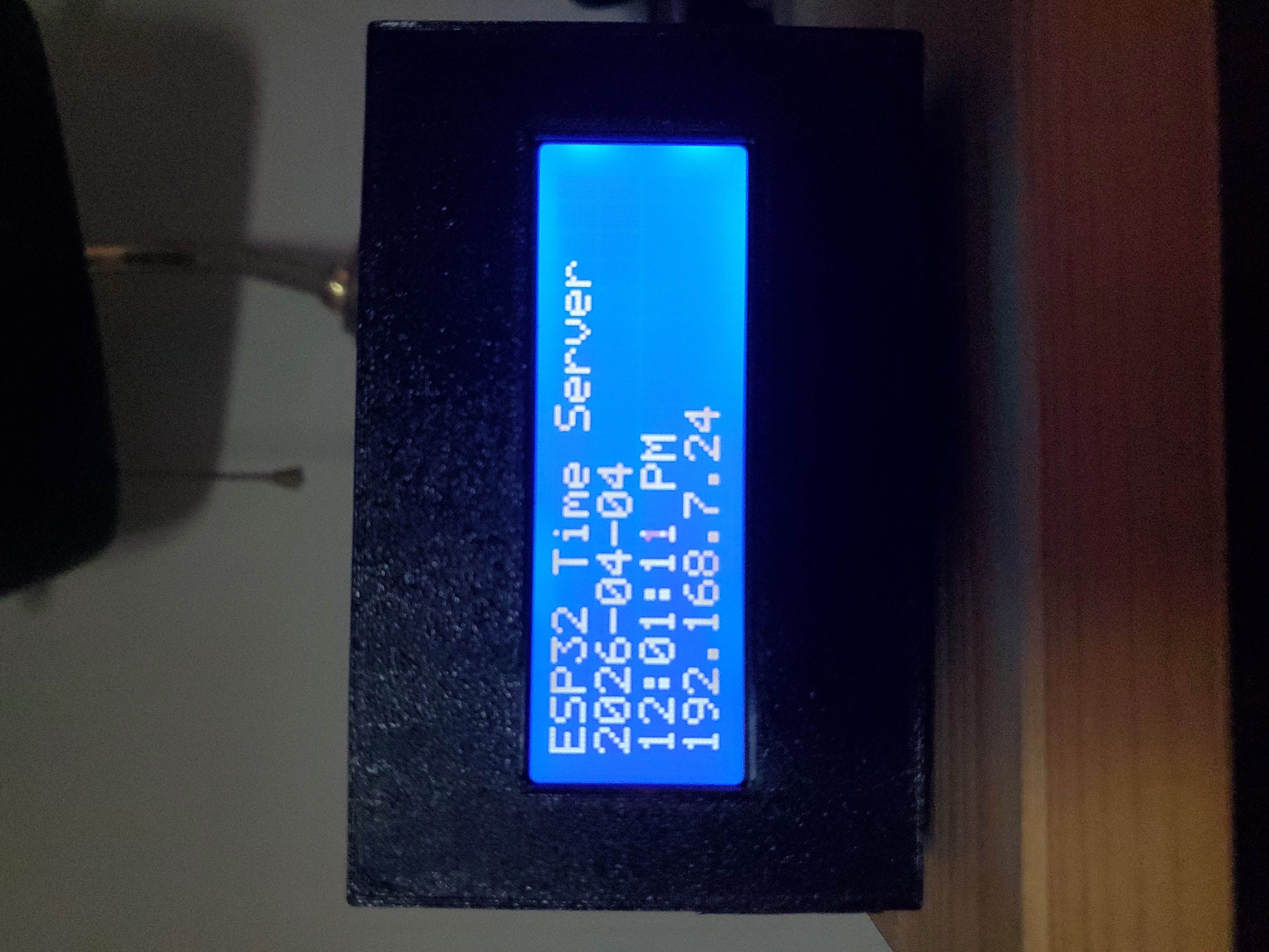
ESP32TimeServer uses a GNSS (North America & Europe) receiver as its time source, making it a true Stratum 1 server — meaning it gets its time directly from satellites rather than from another server. Every device on your home network can then synchronize to it for highly accurate local time.
ESP32TimeServer supports Waveshare ESP32-P4 Ethernet dev boards and the ESP32-S31 Function CoreBoard-1.
Version 4 brings the following changes:
Support for the ESP32-S31 (preview) chip which provides for Gigabit Ethernet. Performance of the ESP32-S31 (preview) chip surpasses the ESP32-P4 rel 1.3 chip, but is below the ESP32-P4 rel 3.2 chip.
Added Precision Time Protocol (PTP) support. The server can now operate as an NTP, PTP Layer 2 (L2), PTP Layer 3 (L3) UDP, or any and all combinations simultaneously.
Both the NTP and PTP L2 protocols support operation with or without authentication. NTP and PTP L2 have independent mixed/authenticated-only policy settings, each defaulting to mixed mode. Additional notes:
added/updated the following companion programs:
(added) ESP32PTPL2Follower ( https://github.com/roblatour/ESP32PTPL2Follower ) an example PTP L2 Follower for the ESP32-P4 and ESP32-S31 platforms
(added) ESP32PTPL3Follower ( https://github.com/roblatour/ESP32PTPL3Follower ) an example PTP L3 Follower for the ESP32-P4 and ESP32-S31 platforms
(added) tools\configTimeSettings.ps1 a python script to automate the setup of native Windows w32time client for use with ESP32TimeServer in either NTP or PTP L3 UDP modes
(updated) ESP32TimeServerTester ( https://github.com/roblatour/ESP32TimeServerTester ) to test PTP L2 and L3 UDP servers
removed use of the Arduino Sparkfun GNSS library (adapting its needed code for use within ESP-IDF) as well as the last vestiges of Arduino code. This was done to support the ESP32-S31 chip which while supported in the ESP-IDF environment is not supported in the Arduino environment (although may be in the future)
added automated regression testing for more information please see here
updates to MQTT messaging for new PTP reporting and to provide for, in most cases, more saved messages in memory when a TF card is not available
updates to Home Assistant configurations for new PTP reporting
added external TF card reader support for the ESP32-S31 as the Espressif Functional CoreBoard - 1 does not have a built in TF card reader
revised leap-second processing aligned to the CGPM's decision to do away with leap-second processing in May 2027 for more information please see here
added read back confirmation of Ublox receiver going in to stationary mode
several other updates and improvements
Version 3 further improvements:
Version 2 was a ground-up rewrite which came with a faster, more capable board support and a long list of accuracy, reliability, and convenience improvements over version 1, including:
MACAddress is a base-MAC override and is applied
before Ethernet starts. For PTP master selection, use the active six-byte
address reported as Active Ethernet MAC at startup; the SDK may derive a
different Ethernet source MAC from the base address.Version 1 described in detail here was built for Arduino / PlatformIO and remains available here.
| Qty | Item |
|---|---|
| 1 | WaveShare ESP32-P4-ETH or ESP32-P4-WIFI6-ETH development board (with or without optional PoE) 1 2, or the experimental ESP32-S31 Function CoreBoard-1. |
| 1 | GPS/GNSS module Recommended: SparkFun GNSS Receiver Breakout - MAX-M10S (Qwiic) 2. Additionally, one project user reported using this MAX-M10N board just fine. Beyond that, support for the GT U16 has been added in version 2.9 - this receiver offers superior reception when coupled with the right antenna (see notes below). Additionally, while some lower-cost generic modules UBlox compliant receivers are supported, those without a PPS pin are not. |
| 1 | GPS/GNSS antenna with SMA connector (SparkFun GPS/GNSS Magnetic Mount Antenna - 3m (SMA)) 2. Alternatively the GT U16 with an L1/L5 antenna offers superior reception. However, in my testing I used the 3M SMA W70C L1/L2/L5 antenna an IPEX to SMA adapter and got very good results (I have the antenna bundled with the GT U16 (link above) on order and when I get it and test it I will update this page). |
| 1 | (Optional) TF Card, formatted as FAT32, if you're using MQTT and want a larger queue, kept through power loss, should broker communications be down 2 |
| 1 | (Optional) RGB LED: KY-016 (AliExpress) or WS2812 (AliExpress) with a 470Ω resistor and optional lens cap (AliExpress) |
| 1 | (Optional) 4×20 I²C LCD display with HD44780 controller with PCF8574 I²C backpack (AliExpress) 2 |
| 1 | (Optional) Momentary push button for displaying up time and triggering a reset (AliExpress) 2 |
| 1 | (Optional) USB C extension cable (with right angle end) (AliExpress) 2 + two M3*8 |
| — | Miscellaneous: Ethernet cable, female dupont connection wires, small 4" .1" zip ties, solder 2 |
| — | A PoE-capable switch, PoE injector, or USB-C power supply and USB-C cable |
⚠️ WARNING — Do NOT power the ESP32-P4-POE-ETH or the ESP32-P4-WIFI6-POE-ETH via both its USB-C connector and a PoE powered Ethernet cable at the same time. Powering from both simultaneously may damage the ESP32-P4-ETH board, PoE switch, or device providing USB power. Either power-supply alone is generally sufficient to power the board, GNSS module, LCD screen, etc. However, if after flashing the firmware and a power recycle the LCD screen blinks on and off for several minutes before coming online its a good indication a power-supply (USB charger or PoE injector) issue. In this case try a different USB charger or PoE injector, being careful to always use only one power-supply at a time.
1 See notes in the 'What's New in Version 2' section above.
2 (Optional) there are 3D Printable Case designed for use with ESP32-P4_ETH and these specific components (for more information see below).
(Also Optional) To cut down on wiring a PCB can be used. One designed
to work within this project's 3D printed enclosure is available in the
PCB folder. If your interested, please review the Readme.md file in
that folder for more information.
| GPS pin | ESP32-P4-ETH pin |
|---|---|
| GND | GND |
| VCC | 3V3 |
| PPS | GPIO 20 |
| TXD | GPIO 21 (RX) |
| RXD | GPIO 22 (TX) |
Pro Tip: (Optionally) Adding a capacitor between the GNSS module's Vcc and GND power pins, placed as close as possible to those pins, can improve GNSS power supply stability. Use a 100nf (aka 0.1μf, aka 104) ceramic capacitor, rated at least 50v, such as this one.
Important:
Some GNSS receivers and breakout boards provide a 3.3v PPS (Pulse-Per-Second) output pin while others provide a 5v PPS output pin.
Only connect a 3.3v PPS pin to an ESP32 GPIO pin, never connect a 5v PPS pin to an ESP32 GPIO pin
For the wire between the ESP32-P4's GPIO pin and the GNSS Receiver's PPS pin use as short and as well connect wire as possible; a standard copper Dupont wire will be fine assuming its gauge is between 24 AWG and 28 AWG
The GNSS GND must be connected to the ESP32 GND
Also of note, the above PPS, TX, and RX pin selections were changed in version 2.4 for better forward and backward compatibility between revisions of the ESP32-P4 chip. However, if an earlier version of the software has been working fine for you then you may be able to use the old pin specifications if you want to avoid rewiring your project. Please see the ESP32TimeServerSettings.h file for more information.
| Button | ESP32-P4-ETH pin |
|---|---|
| One terminal | GND |
| The other terminal | GPIO 3 |
| LCD pin | ESP32-P4-ETH pin | |
|---|---|---|
| GND | GND | |
| DI | 470Ω resistor | GPIO 4 |
| 5v | V5 / VBUS |
Important with the WS2812 a 470Ω resistor is require between the DI and GPIO 4 pin
| LCD pin | ESP32-P4-ETH pin |
|---|---|
| GND | GND |
| BLUE | GPIO 4 |
| GREEN | GPIO 5 |
| RED | GPIO 6 |
| LCD pin | ESP32-P4-ETH pin |
|---|---|
| GND | GND |
| VCC | 3V3 |
| SLC/SCL | GPIO 7 |
| SDA | GPIO 8 |
Refer to the pin definitions in
main/ESP32TimeServerSettings.h.
The following are GPIO numbers and the board's corresponding J2 header pin numbers, Note board silk screen numbering (J2 pins) do not correspond with the GPIO pin numbering:
| Peripheral connection | S31 GPIO | J2 pin |
|---|---|---|
| GNSS receiver RX (MCU TX) | 22 | D2 |
| GNSS receiver TX (MCU RX) | 21 | D1 |
| GNSS PPS input | 20 | D0 |
| LCD SDA | 38 | 22 |
| LCD SCL | 39 | 21 |
| Uptime/reset button | 40 | 19 |
| Onboard addressable LED | 60 | 6 |
| Optional KY-016 blue / green / red | 46 / 47 / 48 | 16 / 13 / 14 |
Use a common ground and 3.3 V GNSS UART and PPS signals. Keep the PPS wire short. Only ever connect the LCD to a 3.3v power pin - never 5v.
Use a reader designed for 3.3 V power and 3.3 V SPI signals, with a FAT32 microSD/TF card. This add-on provides the same persistent MQTT backlog as the P4's onboard socket; it is not required for time serving. The GNSS, LCD, button, LED options, Ethernet, and internal PPS loopback retain their existing pins.
| Reader pin | S31 connection |
|---|---|
| 3.3V | 3V3 power |
| CS | GPIO0 |
| MOSI | GPIO1 |
| CLK | GPIO2 |
| MISO/MOSO | GPIO3 |
| GND | GND |
MOSO is sometimes a misprint for MISO (reader output, MCU input);
confirm this in the reader's documentation.
Keep the connecting wires to the TF Card reader short.
Insert the card before power-on; mounting is attempted once at startup. An absent, non-FAT32, or unusable card falls back to the existing RAM queue without formatting the card.
Power sharing: J2 pins 35 and 36 are connections to the same 3.3 V rail, not two independent supplies and not GPIO signal pins. The LCD and TF reader can share one 3V3 header connection using a suitable power distribution connector, with common ground, provided the board regulator, supply, and wiring can handle the total load, including the GNSS and card write-current peaks. The number of power pins does not establish available current; check the reader/card and LCD specifications and the board's remaining current budget. A 100 nF ceramic capacitor plus a suitable bulk capacitor (for example 10–47 uF) near the reader can help with transients, but cannot compensate for an undersized supply.
Do not connect a reader's 3.3V pin to 5V, directly or through a resistor or resistor divider.
A downloadable 3D printable enclosure designed for use the WaveShare
ESP32-P4-ETH (with or without the POE hat) + Sparkfun GPS boards is included in
the 3D printable case/ folder. Both .stl
(print-ready) and .f3z (Fusion 360 editable source) files are provided so you
can tweak the design to suit your needs.
Note: the 3D printable enclosure files also includes the needed models for version 1 (used an Olimex ESP32-PoE-ISO Rev. B dev board).
The existing PCB and cases were designed for the Waveshare boards; they are not claimed to fit the S31 Function CoreBoard.
To build and flash ESP32TimeServer you will need Espressif's ESP-IDF v6.1 or above. If you don't already have this software installed, just follow the install instructions directly below:
https://docs.espressif.com/projects/esp-idf/en/stable/esp32/get-started/index.html
which include these links to get it:
Installation of ESP-IDF and Tools on Windows
Installation of ESP-IDF and Tools on Linux
Installation of ESP-IDF and Tools on macOS
If you want to further develop the project, Visual Studio Code with the ESP-IDF extension is recommended. However, they are not needed to build and flash the project - the instructions for that are below.
Both Visual Studio Code (Community Edition) and the ESP-IDF extension are free to download and use. Here is where you can find more information about them and get your copies:
A kind user of this project has shared more detailed environment setup, build and flash instructions specific to Linux (Debian 13) - these can be found here
Dependencies are resolved by the ESP-IDF Component Manager from
main/idf_component.yml:
esp-idf-lib/hd44780 and esp-idf-lib/pcf8574.jef-sure/hd44780, which supports the existing PCF8574 wiring.espressif/mqtt, espressif/mdns, and espressif/led_strip.The initial S31 build used ESP-IDF 6.1.0, jef-sure/hd44780 0.1.3,
espressif/mqtt 1.1.0, espressif/mdns 1.14.1, and
espressif/led_strip 3.1.1. Component versions are resolved independently for
each build directory and may change within the declared version constraints.
If PSRAM is enabled but boot initialization is disabled, set
CONFIG_SPIRAM_BOOT_HW_INIT=y and
CONFIG_SPIRAM_PRE_CONFIGURE_MEMORY_PROTECTION=y for delayed initialization.
The native path follows CONFIG_SPIRAM_USE_MALLOC even if the former Arduino
CONFIG_ARDUINO_ISR_IRAM option is enabled. This differs from Arduino's
initializer; the optional path has not yet been validated on hardware.
Note: The ESP-IDF Component Manager resolves these dependencies dynamically at build time. Each build directory has its own generated
dependencies.lock; it is not a shared cross-target lock.
Create a folder for this project and clone this repository into it. For example:
c:mkdir c:\temp\ESP32TimeServerProjectcd \temp\ESP32TimeserverProjectgit clone https://github.com/roblatour/ESP32TimeServercd ESP32TimeServerAll user-configurable settings — GPIO pins, GPS options, LCD options, button support, time zone, etc. — are centralized in:
main/ESP32TimeServerSettings.hEdit this file to match your desired hardware setup before building. The
ESP-IDF target selected by the build profile chooses the P4 or S31 GPIO branch
automatically; no separate board-name string selects the compiler target.
For a UART console, serialMonitorSpeed sets its baud rate. USB Serial/JTAG
does not use this value; UART1 is reserved for the GNSS receiver and cannot be
selected as the console.
Note: The settings file indicates whether certain features are enabled. These include support for an Uptime/Restart Button, a Liquid Crystal Display, MQTT reporting, and Over the Ethernet Updates. Please also note, that if a Liquid Crystal Display is not connected,
LIQUID_CRYSTAL_DISPLAY_ENABLEDmust be0(disabled) or a critical runtime error will occur.
For a PTP-capable retrofit build, see the PTP settings. These are compile-time choices, not MQTT commands. Keep your existing pins, GNSS, addressing, secrets, display, and native OTE configuration rather than copying the donor settings file.
Open a Command Prompt at the repository root and load the ESP-IDF 6.1
environment. The first build downloads the Component Manager dependencies into
managed_components.
call C:\esp\v6.1\esp-idf\export.batConnect the board, then identify the chip model and revision:
python -m esptool -p COMx chip-idReplace COMx with the actual port. Select the model first; an S31 revision
number must not be interpreted as a P4 revision. For ESP32-P4, choose the
matching profile:v
| Chip revision | Profile | Build directory |
|---|---|---|
| P4 before v3.0 | pre_v3 | build_pre_v3 |
| P4 v3.0 | v3_0 | build_v3_0 |
| P4 v3.1 or later | v3_1 | build_v3_1 |
| ESP32-S31 Function CoreBoard 1 | s31 | build_s31 |
For example:
python .\tools\build.py --profile v3_1Use --profile v3_0 or --profile pre_v3 for the other P4 profiles, or
--profile s31 for the S31. The helper supplies --preview for S31. Each
profile keeps its generated sdkconfig inside its own build directory. The
helper does not flash, delete the existing root sdkconfig, or run
set-target on incremental builds. It rejects a build directory configured
for a different target or revision. Use --build-dir .\my_build to choose a
different workspace-local directory, --define NAME=VALUE to add a CMake
definition, and --reconfigure when reconfiguration is intentional.
For an equivalent initial raw v3.1 build, use a fresh directory:
idf.py -B .\build_v3_1 ^
  -D IDF_TARGET=esp32p4 ^
  -D SDKCONFIG=.\build_v3_1\sdkconfig ^
  -D "SDKCONFIG_DEFAULTS=sdkconfig.defaults;config\esp32p4_rev_v3_1.defaults" ^
  build
For the other revisions, substitute their profile directory, generated
sdkconfig, and matching file under config. ESP-IDF also applies
sdkconfig.defaults.esp32p4, including the P4's 32 MB flash. The equivalent
fresh S31 build is:
idf.py --preview -B .\build_s31 ^
  -D IDF_TARGET=esp32s31 ^
  -D SDKCONFIG=.\build_s31\sdkconfig ^
  -D "SDKCONFIG_DEFAULTS=sdkconfig.defaults;config\esp32s31_function_coreboard_1.defaults" ^
  build
Preserve existing customized configurations; defaults do not
override options already selected in them.
Performance optimization must remain explicitly selected in an existing sdkconfig.
In the same Command Prompt where ESP-IDF 6.1 was loaded:
idf.py -B .\build_v3_1 -p COMx flash monitorFor S31, use its matching output directory and preview flag:
idf.py --preview -B .\build_s31 -p COMx flash monitorNote: Replace
COMxwith your actual serial port. For example: COM6Use the directory for the profile you built. Do not use
--forceto flash an image to the wrong chip or an earlier ESP32-P4 revision.
On S31, select the port for the board's USB Serial/JTAG or USB-to-UART
connection. Keep programming pins separate from the GNSS UART pins. The
application images are build_<profile>\ESP32TimeServer.bin; P4 and S31
images, and images with different P4 revision requirements, are not
interchangeable.
Following the initial flash, OTE updates can be performed if
OTE_UPDATES_ENABLED was set to 1 (Enabled) for the initial build and flash.
For more information, please see UsefulPowerShellCommands.md.
OTE checks the image chip and revision before starting the update. Verify
cross-target and incompatible-revision rejection on the actual device; never
bypass those checks.
To make use of ESP32TimeServer on your network /systems please see here
Once running, and with your Network and System changes setup, you can validate accuracy at https://time.is.
This is only a basic connectivity check. Native GNSS, S31 Ethernet and accessories, NTP/PTP hardware timestamps, and timing accuracy require the physical acceptance and load measurements listed in the S31 plan. They remain pending for Phase 2.
You're also welcome to use this open source software (also developed by me) to stress test your time server:
https://github.com/roblatour/TimeServerStressTest
This project is released under the MIT License — see the LICENSE file for details.
To help support this project, or to just say thanks, you're welcome to 'buy me a coffee'.

Copyright © 2026 Rob Latour
| Qty | Value | Footprint | References |
|---|---|---|---|
| 2 | Conn_01x20_Socket | Connector_PinSocket_2.54mm:PinSocket_1x20_P2.54mm_Vertical | Left1, Right1 |
| 2 | MountingHole_3.2mm_M3 | MountingHole:MountingHole_3.2mm_M3 | REF1, REF2 |
| 1 | Conn_01x02 | Connector_JST:JST_PH_B2B-PH-K_1x02_P2.00mm_Vertical | Button1 |
| 1 | Conn_01x04 | Connector_JST:JST_PH_B4B-PH-K_1x04_P2.00mm_Vertical | LCD1 |
| 1 | Conn_01x08_Socket | Connector_PinSocket_2.54mm:PinSocket_1x08_P2.54mm_Vertical | GPS1 |
It measures 102 × 80 mm and has 2 copper layers, 1.6 mm thick.
7 parts. The full list of its parts is on this page, with links to each part's symbol and footprint where PCBKit's library has them.
From the roblatour/ESP32TimeServer repository on GitHub, at the commit this page was made from: the board is PCB/KiCad/ESP32TimeServer.kicad_pcb and its schematic PCB/KiCad/ESP32TimeServer.kicad_sch. PCBKit opens the board in the browser, with nothing to install.
Its repository publishes it under the MIT licence: you may reuse it on that licence's terms (keep the author's notice, and for a copyleft licence share your changes alike).
byrantech/laptop
anyon_e, a highly integrated, high end, open source laptop. Attempt the impossible.


AxxAxx/AxxSolder
STM32 Based soldering station for JBC cartridges, 9-24 VDC and USB-PD power


jamro/tiny-engineer
A small desktop robot that brings an AI coding assistant to life, physically acting out when it reads files, thinks, writes code, and finishes work.

hoglet67/RGBtoHDMI
Bare-metal Raspberry Pi project that provides pixel-perfect sampling of Retro Computer RGB/YUV video and conversion to HDMI
