Skip to the content
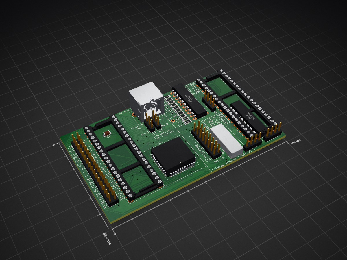
2 layers100 × 58.5 mmMainboard 8x16 multi USB, the printed circuit board in 3D

Mainboard 8x16 multi USB

roberto314/UniversalKeyboardAdapter1

a replacement USB Keyboard for Retro Computers. Supports serial, parallel, matrix and PS2 - like protocols.

Size
100 × 58.5 mm
Copper layers
2
Thickness
1.6 mm
Parts
44
Nets
111
Pads
355
Tracks, vias
1,222, 120
Pours
1
Routed
Yes
KiCad
KiCad 9.0 (file 20241229)
Created
16 Jun 2026
Updated
16 Jun 2026

Overview

Mainboard 8x16 multi USB is an open-source printed circuit board by roberto314, from the roberto314/UniversalKeyboardAdapter repository on GitHub, published under the BSD-2-Clause licence. It is a 2-layer board of 100 × 58.5 mm with 44 parts on 111 nets, routed with 1,222 tracks and 120 vias.

It is built around the 74LS245SC. Its parts include 11 resistors, 11 connectors, 8 diodes, 5 ICs and 4 capacitors. It belongs with the keyboards and input and computers and single-board computers boards and the STM32 boards of this library.

Main components

1

README

README.md

Universal Keyboard Adapter

A USB Keyboard to Retro Computer Adapter with focus on universality and longeivity.

Version: 1.28 (Software), 3.21 (Hardware)

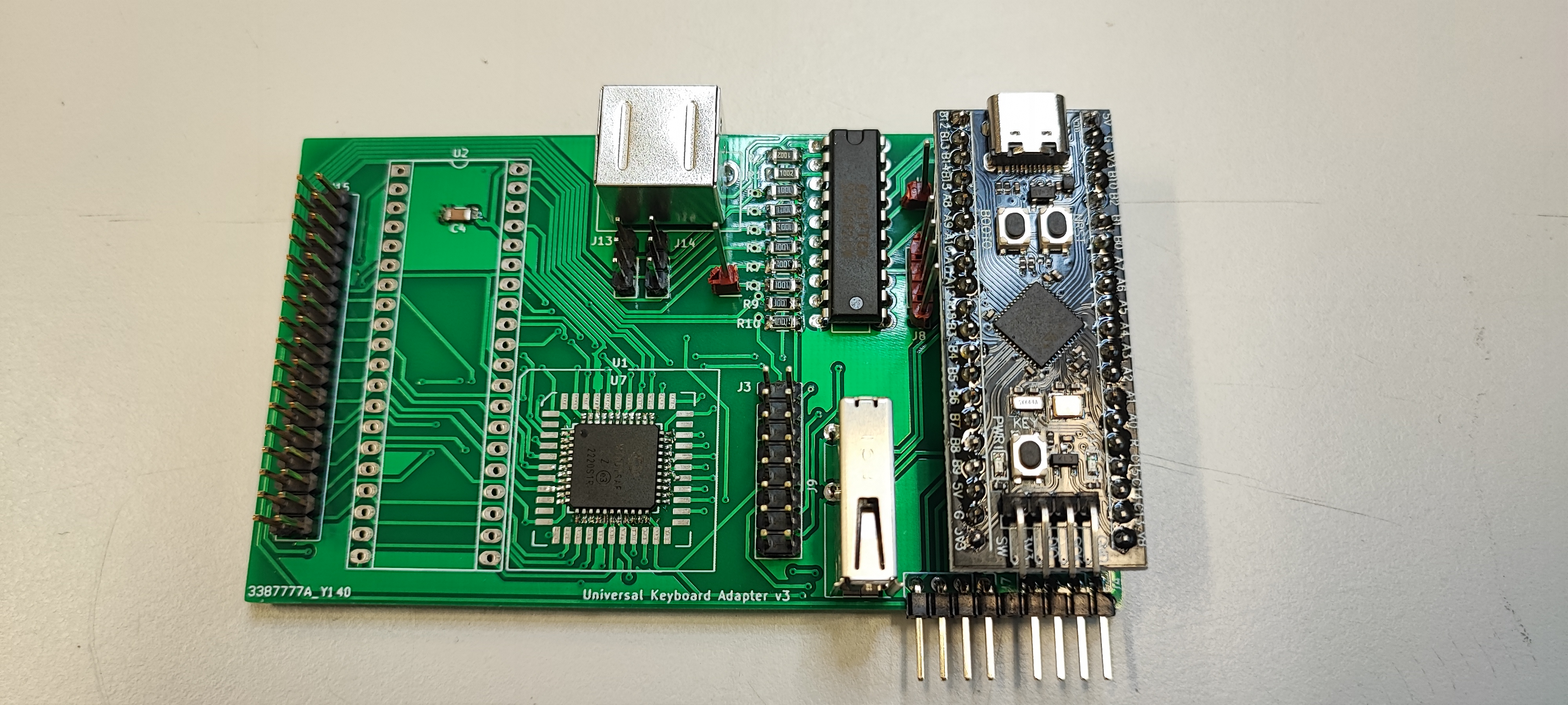
Universal Keyboard Adapter v3

Why another Keyboard Adapter?

Because many of the solutions use a "small" PIC or Atmel microcontroller and have to use PS2 Protocol. I wanted something with USB because you can use wireless keyboards (i know there are wireless PS2 KBs), and modern solutions like your own keyboard with QMK or TMK firmware or nice mechanical KBs. Also if you have more than one "Retro-Computer" it could get quite costly if you need more than one converter.

To read the PS2 Scancodes a small Hardware modifikation can be necessary! Readback is now on B13,B14.

What works now?

  • Matrix keyboard (like Commodore 64, 128, VIC20, Amstrad CPC, Sinclair ZX81,....)
  • Parallel Output (like Apple II (europlus - maybe others as well), Apple I)
  • IBM XT (with adjusteable key repeat)
  • IBM XT Read Scancodes
  • Amiga 2000 (probably also 1000, 3000 and 4000)
  • Amiga 2000 Read Scancodes
  • IBM AT Read Scancodes
  • Generic UART (Thomson TO9, some Terminals, CP/M)
  • EPROM Storage (you need an EPROM Chip on the Blackpill Board! I use a Winbond W25Q64 or a Winbond W25X20).
  • Key repeat feature with configureable Wait and Delay (for now only with IBM XT and Matrix)
  • Type and Paste from Serial Terminal and act as keystorkes
  • Spreadsheet Template for simpler mapping - can be parsed with python, see next point.
  • Python script (map_it.py) to read spreadsheet and generate keycodes and config file to upload.

What will work soon?

  • IBM AT (PS2)

What are the features?

  • fully configureable via serial port (there is a command shell and an interactive menu),
  • up- and downloadeable keymaps (ASCII Text with checksum),
  • one can store more than 1000 keymaps in FLASH EPROM and change with keys or serial port,
  • works with: dumb keymatrix (Commodore VIC20, C64, C128, Atari 400, 800, XL, XE, Osborne and many more),
  • true n-n mapping (any combination of modifier plus up to two keys can be mapped to up to eight output switches),
  • open source and open hardware (schematics in kicad 6, code in C),
  • RTOS with HAL so poratble (even if the microcontroller is not available a port is quite easy),
  • Uses ChibiOS as RTOS and HAL from ChibiOS, USB Host from ChibiOS - Community,
  • Hardware can be a STM32F411 or a F401 "Blackpill" Board which is now about €13.- or €6.- and a board with two 74HC245 Buffer, a Matrix Switch and a FLASH Chip,
  • The Matrix Switch can be MT093, MT8812 or MT8816 in DIL, PLCC or TQFP (8X12 or 8x16 Matrix) and should work on any Keymatrix,
  • Code is developed with Chibi Studio 20 (trunk version),
  • Up to four locking keys - any regular key can be a 'locking' key,
  • Fallback key - If a Key plus modifier is not, found the key without modifier is taken,
  • Remap function can change an existing scancode and modifier OR an existing keycode,
  • Remap function can also add a new scancode/modifier/keycode combination,
  • Function to add modifier to already mapped keys (mapfk),
  • Read Scancodes from connected keyboard (without Computer) for PS2 like protocols (AMIGA, IBM XT, IBM AT) (enter debug mode with "d+b"),

planned additional features

  • UART like communication (CP/M, some Terminals,...).
  • macro feature (send a text from any key)
  • display to show the stored keymaps
  • Mouse replacement with touchpad or optical mouse

What is to see here?

  • most recent version is in schematics/Mainboard_8x16_multi_USB.
  • in codes is the workspace folder from the eclipse project. Copy it to your workspace_trunk folder in your ChibiStudio_20 Download. There is no install necessary.
  • IMPORTANT! In the Project folder is a subfolder "copy this". Read the Readme inside this folder and copy the files accordingly.
  • in computer info are pinouts and info for some keyboards.

User Manual

What goes where

  • J4 is the Debug Serial Port. Connect this to your Computer. On v3 the rightmost Pin (near the edge) is Pin 1. Pin1-GND, 2-TX, 3-RX, 4-5V.
  • J15 is the conn. to the Retro Computer. Pin 1 is top left. Pinout (see schematic in Mainboard_8x16_multi_USB) is: Pin 1: +5V, Pin 2,4,6,8,...: COL 0,1,2,3,..., Pin 34: GND, Pin 33,31,29,27,25,...: ROW 0,1,2,3,..., Pin 3,5,7,9: Parallel Output
  • J3 is for Apple with Apple II Pinout.
  • J13 and J14 is KBD_CLK and KBD_DAT on PS2 Connector.
  • JP1 and JP2 (back): change is only needed for MT8812 in PLCC Package (see datasheet and schematics)
  • JP3 (back): 3.3V or 5V RS232 TX
  • JP4 (back): TX or PB14 to buffer
  • JP5 (back): 3.3V or 5V Power for I2C (J7)
  • J7: I2C Port (not used at the moment).

--- USE ONLY ONE 5V INPUT WHEN A COMPUTER IS CONNECTED TO EITHER PORT! --- That means no additional 5V Source.

The Serial Speed is 115200 8N1 with 3.3V Level. If you open a serial Port with a terminal emulator program (Realterm on Windows or picocom on linux) you'll get a prompt which looks like this: "ch> ".

How to interact with the Adapter?

With "help" you get a list of builtin commands. If you connect a Keyboard to the USB Port you get a Message like

"00316.849 HID: Connected, HID0" - that means the keyboard is recognized. If on the other hand you get:

"00151.938 Unable to load driver." - the Keyboard cannot be used.

If you press "d" and "b" BOTH at the same time you'll get additional debug output. Successful entry to the configuration menu is shown at the increased blinking speed of the blue LED.

You get an output like this:

text
 -------------------------------
 Scancode1 04 with modifier 00 entered 
 Length of output codes1: 01           
 code: 10                              
 Output Data: 10 active: 01            
 Output Data: 10 active: 00            
 Keycode1 found at offset: 0016        
 Locking Key: 0000                     
 matrix store one key first place: 10  
 matrix release one key first place: 10

This means a mapped Output code is found. If you get this however:

text
 -------------------------------
 Scancode1 35 with modifier 00 entered 

no output is mapped.

The Output means the following: Scancode1 04 with modifier 00 is the HEX Code from the USB Keyboard.

modifier 00 is the modifier bits (1-CTRL, 2-SHIFT, 4-LALT, 8-LWIN, 10-NUMLOCK, 20-CAPSLOCK, 40-RALT, 80-RWIN) these can be found in keyboard_usb.h.

Length of output codes: 01 means one byte output code: 10 with code 0x10. Output Data: 10 active: 01 Output 10 has been activated (Switch turned on). Output Data: 10 active: 00 Output 10 has been deactivated (Switch turned off).

Keycode1 found at offset: 0016 Offset in map where the scancode and modifier has been found.

  • for further debugging te function "readmap 0x16" outputs the map entry for this scancode (04)

Maximum size of data is 4056 byte, one entry is at least 4 byte but can be 8 byte.

Builtin functions

  • help - shows all builtin functions
  • echo - nothing useful
  • readmap - dumps only the map entry at adress. Usage readmap [OFFSET]
  • dumpee - dumps 128 byte of the onboard EPROM. Usage: dumpee [STARTADDRESS]
  • writee - writes data to EPROM. Usage: writee [ADDRESS] [DATA]
  • clrpee - Clears one Page (4k) of EEPROM at Address. Usage: clrpee [ADDRESS]
  • remap - changes the mapping for a key
  • dumpcon - dumps the config over serial. Usage: dumpcon (Text Output only the used slots) or dumpcon 1 (total config - to archive or to receive via getcon) or dumpcon 2 for dump in c-code format.
  • getcon - receives config over serial link. DON'T USE UNLESS YOU CAN PROVIDE A CONFIG FILE. Press Reset to exit (all config is lost).
  • kwiz - keyboard wizard. An interactive menu to map keycodes. This is now split to header and kwiz, where header just modifies the header data and kwiz modifies only the mapping.
  • mapfk - maps modifier keys to already mapped keys.
  • paste (1|2) - paste text into terminal window and transfer it to Retro-computer (only Keyboard Characters supported). Exit with Backspace or any other non-mapped key (see conversion.h). English and German Layouts supported now.

How to get started (Matrix Keyboard)

  • connect Rows and Columns to J15. Start with ROW0 and COL0 and fill all the Rows and Column Lines starting from zero. Don't leave lines unconnected inbetween. You can however leave lines open at the end.

For example: If you have an 8x8 Matrix connect ROW0 to ROW7 and COL0 to COL7.

  • connect GND and +5V
  • connect other lines (like RESET or CLR,...). These Lines pull to GND (or VCC) and can be configured (depending on parts soldered to the board) as Open Collector or Push-Pull.

How to map keys?

  • If there is an Eprom on the board, load an empty keymap (config mode, F12)
  • configure the header with "header" and follow the instructions.
    • Output Type is 1-GENERIC_GENERIC_UART, 2-APPLE, 3-GENERIC_MATRIX, 4-IBMXT, 5-AMIGA, 6-IBMAT (mapping.h)
    • Keyrepeat
    • Parallel output idle state (also used for PS2 polarity)
    • name your map (no spaces allowed and <= 32 characters!)
  • Then start "kwiz" via serial console.
    • now use + and - to circle through the free keycodes the Retro-Computer shows a character
    • press the corresponding key on your USB-keyboard
    • map only keys without (input) modifier
    • with i one can identify a (output) modifier key
    • it works by sending a potential modifier code befor the regular code. It should look like a pressed modifier + key on the Retro-Computer.
    • press x to exit
  • check the keys
  • enter mapfk input_modifier output_modifier to add all the modifier keys to the already mapped keys.

How to handle EPROM?

  • EPROM can be a Winbond 25X or 25Q Series with 1-64MBit. (maybe more look in eprom.c and eprom.h)

    • if EPROM is NOT a Winbond you have to adjust eprom.c and eprom.h, the device Must have a sector erase of 4kB with id 0x20 because the maps are 4k.
  • the last 4k Page is used to store the last used map (16bit). If a value == 0xFFFF is found it uses the value before as the map id.

  • Maps are 4kB each.

  • If no EPROM is found the values from the internal ROM are used.

  • to store the map to EPROM in config Mode: (press c + o on the keyboard, watch the LED blink fast)

    • Press F11: stores only the last used map - no mapdata!. This map gets loaded at power-up.
    • Press SHIFT + F11: Stores mapdata to a NEW position and stores last used map.
    • Press CTRL + F11: Stores mapdata to the FIRST Position of a map with the same name!
  • Changing a map is in config mode:

    • Press F1 (for map 1) to F10 (for map 10), SHIFT + F1-F10 for map 11-20, CTRL + F1-F10 for map 21-30, ALT + F1-F10 for map 31-40 and SHIFT + CTRL + F1-F10 for map 41-50.
    • Press F12 for next map
    • Press F12 + SHIFT for previous map
  • To change data in the header of a map simply use "kwiz" change the data and the exit with "x". Check with dumpcon for correct inputs and save the map in-place with CTRL+F11 in config mode.

  • To load the hardcoded data and NOT the Eprom content delete simply the last Page in the Eprom. The info comes at startup:

    text
    Winbond W25X Series found. Size: 2 MBIT.
    Looking for last stored map from    3F000 to    3F0FF
    Found stored map address at pos:    3F00C
    Loading map from EPROM @        0
    keymap TRS-80_MC10_GER loaded.

In this case clrpee 0x3F000 deletes all the entries without deleting the data. It is still possible to load maps with F12 or SHIFT + F12 in config mode. If one wants to load a map again at startup just press F11 in config mode.

How to set up my build environment?

  • Download ChibiStudio 20 for Windows or Linux

  • Get Universal Keyboard Adapter Files

  • Copy the code folder into the workspace_trunk folder of your ChibiStudio instalation

  • In the linux version open the file ChibiStudio-GCC9.2.1 in the root folder of ChibiStudio and fix your PATH (not necessary if you used ~/ChibiStudio).

    • alternatively fix the path for the other compiler versions too.
  • Copy the contents of the folder "copy this" inside the code folder to their respective locations. (Readme.txt is your friend)

  • Start ChibiStudio now and delete all the projects on the left side. They don't work in linux anyway.

  • Import the existing Project into workspace.

  • Open the Project by double-click on the name. There should be a small triangle left of the name now.

  • Try compiling now. Either right-click on the name and select "Build Project" or use the Hammer Symbol in the menu bar.

  • If all works well (no errors), you are set.

  • Programming can be set up in "Run/External Tools/External Tools Configurations".

    • in the Main Tab in Location enter the st-flash path (or a windows equivalent)
    • in working directoy enter: "${project_loc}" (no quotes)
    • in Argument enter: "--format ihex write build/ch.hex" (no quotes)
    • in the Common Tab check Display in favorites menu - checkbox "External Tools"

How to configure my build?

  • There is information in the Readme.txt in the project (=code folder) folder. Basically there is the Makefile where one can select the MCU (F401 or F411) and the Matrix Switch (MT8812 or MT8816).

Parts

44
QtyValueFootprintReferences
91kResistor_SMD:R_1206_3216Metric_Pad1.30x1.75mm_HandSolderR3, R4, R5, R6, R7, R8, R9, R10, R11
81N4148Diode_SMD:D_1206_3216Metric_Pad1.42x1.75mm_HandSolderD1, D2, D3, D4, D5, D6, D7, D8
4100nCapacitor_SMD:C_1206_3216Metric_Pad1.33x1.80mm_HandSolderC1, C2, C3, C4
210kResistor_SMD:R_1206_3216Metric_Pad1.30x1.75mm_HandSolderR1, R2
274LS245Package_DIP:DIP-20_W7.62mm_LongPadsU3, U4
2Conn_01x03Connector_PinHeader_2.54mm:PinHeader_1x03_P2.54mm_VerticalJ13, J14
18812/8816Jumper:SolderJumper-3_P1.3mm_Bridged12_RoundedPad1.0x1.5mmJP1
18816/8812Jumper:SolderJumper-3_P1.3mm_Bridged12_RoundedPad1.0x1.5mmJP2
1Apple IIConnector_PinHeader_2.54mm:PinHeader_2x08_P2.54mm_VerticalJ3
1Conn_01x01Connector_PinHeader_2.54mm:PinHeader_1x01_P2.54mm_VerticalJ6
1Conn_02x17_Odd_EvenConnector_PinHeader_2.54mm:PinHeader_2x17_P2.54mm_VerticalJ15
1DEBUGConnector_PinHeader_2.54mm:PinHeader_1x04_P2.54mm_VerticalJ4
1I2CConnector_PinHeader_2.54mm:PinHeader_1x04_P2.54mm_VerticalJ7
1I2C VoltageJumper:SolderJumper-3_P1.3mm_Bridged12_RoundedPad1.0x1.5mmJP5
1MT8816_DIPPackage_DIP:DIP-40_W15.24mm_Socket_LongPadsU2
1MT8816_PLCCPackage_LCC:PLCC-44_SMD-SocketU1
1MT8816_TQFPPackage_QFP:TQFP-44_10x10mm_P0.8mmU7
1Mini-DIN-6PS2_mini_din_6:MINI-DIN-6-FULL-SHIELDJ12
1ReserveJumper:SolderJumper-3_P1.3mm_Bridged12_RoundedPad1.0x1.5mmJP4
1STM32F411Package_DIP:DIP-40_W15.24mm_Socket_LongPadsJ1
1TX VoltageJumper:SolderJumper-3_P1.3mm_Bridged12_RoundedPad1.0x1.5mmJP3
1UARTConnector_PinHeader_2.54mm:PinHeader_1x04_P2.54mm_VerticalJ8
1USB_AConnector_USB:USB_A_Wuerth_614004134726_HorizontalJ9

More from roberto314/UniversalKeyboardAdapter

2
  • 2 layers74.5 × 58.5 mmUniversalKeyboardAdapter, the printed circuit board in 3D

    UniversalKeyboardAdapter

    roberto314/UniversalKeyboardAdapter

    a replacement USB Keyboard for Retro Computers. Supports serial, parallel, matrix and PS2 - like protocols.

    40 parts1BSD-2-Clause
  • 2 layers13 × 25.9 mmAppleAdapter, the printed circuit board in 3D

    AppleAdapter

    roberto314/UniversalKeyboardAdapter

    a replacement USB Keyboard for Retro Computers. Supports serial, parallel, matrix and PS2 - like protocols.

    3 parts1BSD-2-Clause

Similar boards

  • 2 layers231.1 × 106.7 mmSnark barker, the printed circuit board in 3D

    Snark barker

    schlae/snark-barker

    A 100% compatible replica of the famed SB 1.0 sound card

    199 parts687
  • 2 layers365.8 × 254 mmRaemixx500, the printed circuit board in 3D

    Raemixx500

    SukkoPera/Raemixx500

    Open Hardware Remake of the Commodore Amiga 500+ Mainboard

    372 parts316
  • 2 layers125 × 98 mm3-in-1, the printed circuit board in 3D

    3-in-1

    mudmin/AnotherMaker

    This is where I will store code snippets for AnotherMaker Videos

    44 parts258
  • 2 layers182.9 × 172.7 mmMulti, the printed circuit board in 3D

    Multi

    homebrew8088/8088-PC-Compatible

    8088 PC XT Compatible

    120 parts238GPL-3.0
  • 2 layers365.1 × 203.2 mmDIAG, the printed circuit board in 3D

    DIAG

    Nakazoto/CenturionComputer

    This is just a simple backup of all the files related to the Centurion that I have stored on my HD. The Wiki itself has far more in-depth information about the Centurion and it's individual cards.

    150 parts172
  • 2 layers135.3 × 106.7 mmAdlib, the printed circuit board in 3D

    Adlib

    schlae/adlib

    Reproduction AdLib Sound Card, OPL2, Circa 1990

    61 parts168
  • 2 layers370.8 × 298.5 mm8 Bit Computer, the printed circuit board in 3D

    8 Bit Computer

    The-Invent0r/8-bit-Computer-PCB

    These are the KiCAD files for my 8-Bit Computer.

    323 parts142
  • 2 layers89.5 × 77.5 mmApple2-IO RPi, the printed circuit board in 3D

    Apple2-IO RPi

    tjboldt/Apple2-IO-RPi

    Apple II expansion card using a Raspberry Pi for I/O

    24 parts140MIT

Questions

How big is the Mainboard 8x16 multi USB PCB?

It measures 100 × 58.5 mm and has 2 copper layers, 1.6 mm thick.

What parts does the Mainboard 8x16 multi USB use?

44 parts, built around the 74LS245SC. The full list of its parts is on this page, with links to each part's symbol and footprint where PCBKit's library has them.

Where can I download the Mainboard 8x16 multi USB KiCad files?

From the roberto314/UniversalKeyboardAdapter repository on GitHub, at the commit this page was made from: the board is schematics/Mainboard_8x16_multi_USB/Mainboard_8x16_multi_USB.kicad_pcb and its schematic schematics/AppleAdapter/AppleAdapter.kicad_sch. PCBKit opens the board in the browser, with nothing to install.

Can I use the Mainboard 8x16 multi USB design in my own project?

Its repository publishes it under the BSD-2-Clause licence: you may reuse it on that licence's terms (keep the author's notice, and for a copyleft licence share your changes alike).