2 layers
Maglev26
Hansolini/Take-home-Maglev-lab
A small lab for students in control engineering to learn control topics at home!
60 parts15MIT

 rmingon/ch32v006-dev-board4
Open-source CH32V006 RISC-V dev board — KiCad hardware (schematic + PCB), USB-C power, 3.3 V LDO, SWD/CH340C, and a PD1 blink example.
Ch32v006-dev board is an open-source printed circuit board by rmingon, from the rmingon/ch32v006-dev-board repository on GitHub. It is a 2-layer board of 25 × 41.3 mm with 26 parts on 40 nets, routed with 275 tracks and 56 vias.
It is built around the CH340C, LM1117S-3.3 and BSS138. Its parts include 11 capacitors, 4 connectors, 3 resistors, 3 ICs and 2 diodes. It belongs with the microcontroller boards boards and the RISC-V boards of this library.


A tiny, open hardware RISC‑V playground.
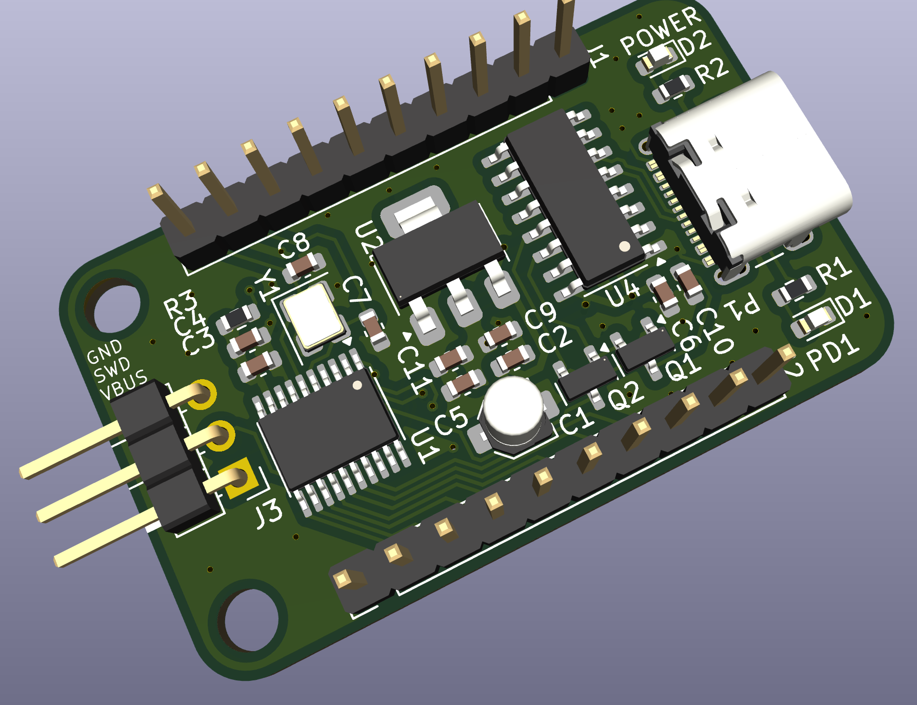
⚠️ This is a hobby/experimental board. Double‑check pin mappings against your MCU datasheet before connecting expensive peripherals.
hardware.kicad_pro – KiCad projecthardware.kicad_sch – Schematichardware.kicad_pcb – PCB layouthardware.kicad_prl – Local KiCad settingspcb.png – PCB view3d.png – 3D renderschematic.png – Schematic snapshotPCB Layout
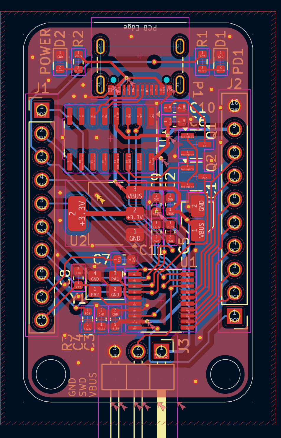
Schematic
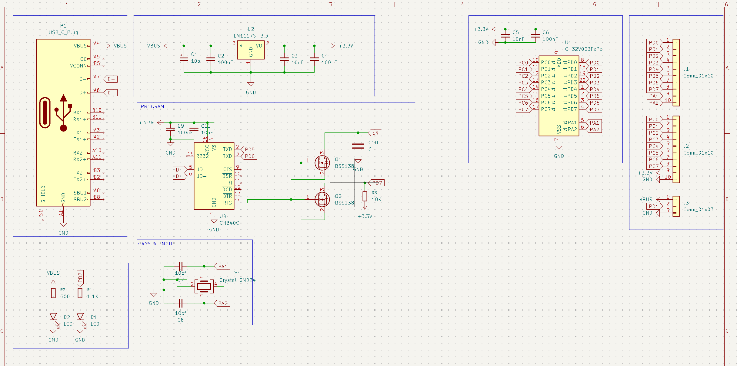
Use any of the following:
ch32v00x.h & register definitions): https://github.com/openwch/ch32v003wch-riscv support (community packages exist).Flashing (recommended): WCH‑LinkE via SWD (Header near the board edge). Serial log: CH340C enumerates as a standard USB‑UART.
// Minimal PD1 blink for CH32V006 using WCH SPL-style headers.
// Requires the WCH SDK providing ch32v00x.h
#include "ch32v00x.h"

static void delay(volatile uint32_t t) {
    while (t--) __asm__("nop");
}

int main(void) {
    // Enable GPIO Port D clock
    RCC->APB2PCENR |= RCC_APB2PCENR_IOPDEN;

    // Configure PD1 as push‑pull output (10 MHz)
    GPIOD->CFGLR &= ~(0xF << (1 * 4));   // Clear PD1 config
    GPIOD->CFGLR |=  (0x1 << (1 * 4));   // MODE=01 (10 MHz), CNF=00 (PP)

    while (1) {
        GPIOD->BSHR = (1U << 1);  // PD1 HIGH
        delay(500000);

        GPIOD->BCR  = (1U << 1);  // PD1 LOW
        delay(500000);
    }
}
Tip: If you’re using the WCH SDK examples, drop this into a template project and adjust the linker script for CH32V006. Build with
riscv-none-elf-gccand flash with WCH‑LinkE.
Hardware and examples are released under the MIT License unless otherwise noted in subfolders.
If you build one, I’d love to see it—PRs and issues welcome!
| Qty | Value | Footprint | References |
|---|---|---|---|
| 4 | 100nF | Capacitor_SMD:C_0603_1608Metric | C2, C4, C6, C9 |
| 3 | 10nF | Capacitor_SMD:C_0603_1608Metric | C3, C5, C11 |
| 2 | 10pf | Capacitor_SMD:C_0603_1608Metric | C7, C8 |
| 2 | BSS138 | Package_TO_SOT_SMD:SOT-23 | Q1, Q2 |
| 2 | Conn_01x10 | Connector_PinHeader_2.54mm:PinHeader_1x10_P2.54mm_Vertical | J1, J2 |
| 2 | LED | LED_SMD:LED_0603_1608Metric | D1, D2 |
| 1 | 1.1K | Resistor_SMD:R_0603_1608Metric | R1 |
| 1 | 10K | Resistor_SMD:R_0603_1608Metric | R3 |
| 1 | 10pF | Capacitor_SMD:C_Elec_3x5.4 | C1 |
| 1 | 500 | Resistor_SMD:R_0603_1608Metric | R2 |
| 1 | C | Capacitor_SMD:C_0603_1608Metric | C10 |
| 1 | CH32V003FxPx | Package_SO:TSSOP-20_4.4x6.5mm_P0.65mm | U1 |
| 1 | CH340C | Package_SO:SOIC-16_3.9x9.9mm_P1.27mm | U4 |
| 1 | Conn_01x03 | Connector_PinHeader_2.54mm:PinHeader_1x03_P2.54mm_Horizontal | J3 |
| 1 | Crystal_GND24 | Crystal:Crystal_SMD_3225-4Pin_3.2x2.5mm | Y1 |
| 1 | LM1117S-3.3 | Package_TO_SOT_SMD:SOT-223-3_TabPin2 | U2 |
| 1 | USB_C_Plug | Connector_USB:USB_C_Receptacle_GCT_USB4105-xx-A_16P_TopMnt_Horizontal | P1 |
Hansolini/Take-home-Maglev-lab
A small lab for students in control engineering to learn control topics at home!


Martins-Lucaas/PRJ-SEMB
Repositório criado para o projeto final da disciplina da SISTEMAS EMBARCADOS da UFU

NabilJomaa22/CE-ESY-assignments
A simple implementation of a Circular Buffer (Ring Buffer) in C. The program reads a user's name, appends the string "CE-ESY", stores it in a circular buffer, then reads it back and verifies that the buffer becomes…


It measures 25 × 41.3 mm and has 2 copper layers, 1.6 mm thick.
26 parts, built around the CH340C, LM1117S-3.3 and BSS138. The full list of its parts is on this page, with links to each part's symbol and footprint where PCBKit's library has them.
From the rmingon/ch32v006-dev-board repository on GitHub, at the commit this page was made from: the board is hardware/hardware.kicad_pcb and its schematic hardware/hardware.kicad_sch. PCBKit opens the board in the browser, with nothing to install.
Its repository states no licence, so its author keeps all rights: ask rmingon before reusing the design.