2 layers50 × 50 mm
Rfid uhf wifi reader
OpenLaundry/wifi-rfid-uhf-reader
Portable long range RFID uhf reader with WIFI based on esp32
23 parts8

 rmingon/OverWire2
Flash and debug STM32 microcontrollers over Wi-Fi. Enterprise-ready ESP32 SWD programming hardware and toolchain integration.
OverWire is an open-source printed circuit board by rmingon, from the rmingon/OverWire repository on GitHub. It is a 2-layer board of 72 × 25 mm with 30 parts on 56 nets, routed with 229 tracks and 57 vias.
It is built around the CH340C, ESP32-WROOM-32 and AMS1117-3.3, with the BSS138 among its other parts. Its parts include 8 capacitors, 8 resistors, 3 ICs, 3 connectors and 2 diodes. It belongs with the radio and wireless and interfaces and adapters boards and the ESP32 boards of this library.


Cut the cord, keep the control. OverWire is a specialized, open-source hardware bridge designed to liberate your STM32 development process. By coupling a powerful ESP32-WROOM-32 module with a dedicated SWD (Serial Wire Debug) interface, OverWire allows you to flash and debug STM32 targets completely wirelessly.
Whether your target is locked inside an enclosure, mounted on a moving robot, or just sitting across the room, OverWire brings the programming interface directly to you over Wi-Fi.
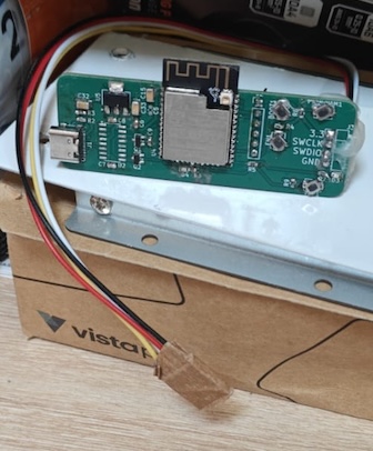
3.3V, SWCLK, SWDIO, GND) ready to hook directly into your STM32 target.EN and BOOT buttons for the ESP32, plus two programmable user buttons (TOP1, PROGRAM1) mapped to IO15 and IO16 for custom firmware triggers.IO12 and IO13 for quick visual feedback (e.g., Wi-Fi connected, Flashing target, Error).| Pin | Name | Description |
|---|---|---|
| 1 | +3V3 | 3.3V Power Output to target (from AMS1117) |
| 2 | SWCLK | Serial Wire Clock (Connects to ESP32) |
| 3 | SWDIO | Serial Wire Debug Data I/O (Connects to ESP32) |
| 4 | GND | Common Ground |
Provides access to 5V, GND, and the ESP32 UART (TX-PROG, RX-PROG) for external communication or secondary programming.
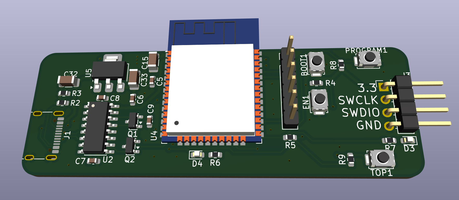
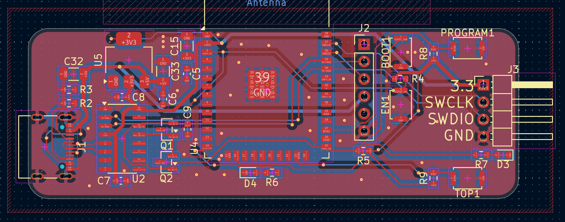
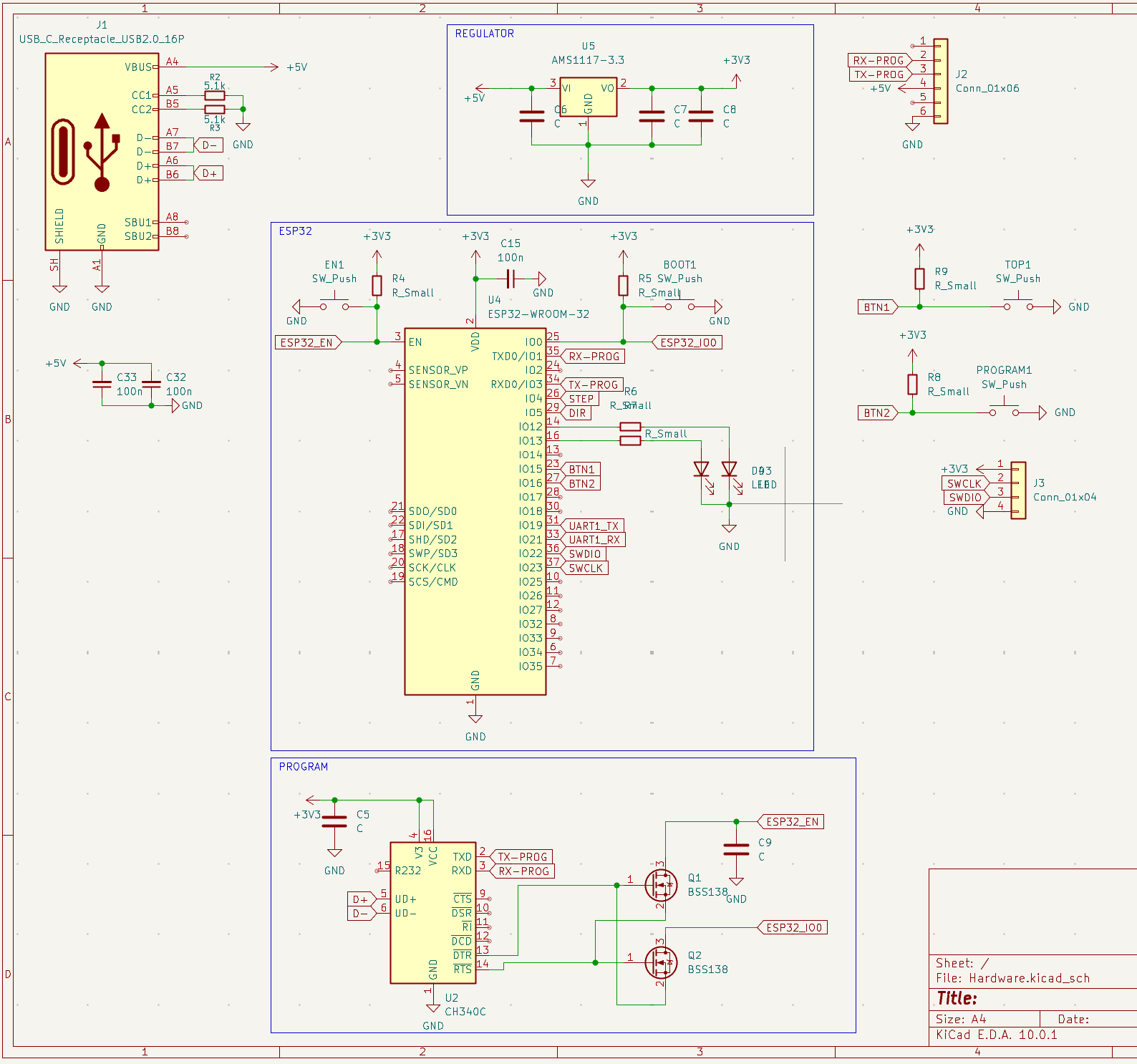
J3 SWD header to your STM32 target.This hardware design is released under the Creative Commons Attribution-NonCommercial 4.0 International (CC BY-NC 4.0) license. You are free to view, use, and modify this design for personal, non-commercial purposes only. You may not use this material for commercial purposes (such as manufacturing and selling the boards) without explicit written permission from the original author.
Designed with KiCad.
| Qty | Value | Footprint | References |
|---|---|---|---|
| 6 | R_Small | Resistor_SMD:R_0603_1608Metric | R4, R5, R6, R7, R8, R9 |
| 5 | C | Capacitor_SMD:C_0603_1608Metric | C5, C6, C7, C8, C9 |
| 4 | SW_Push | Button_Switch_SMD:SW_Push_SPST_NO_Alps_SKRK | BOOT1, EN1, PROGRAM1, TOP1 |
| 3 | 100n | Capacitor_SMD:C_1206_3216Metric | C15, C32, C33 |
| 2 | 5.1k | Resistor_SMD:R_0603_1608Metric | R2, R3 |
| 2 | BSS138 | Package_TO_SOT_SMD:SOT-23 | Q1, Q2 |
| 2 | LED | LED_SMD:LED_0603_1608Metric | D3, D4 |
| 1 | AMS1117-3.3 | Package_TO_SOT_SMD:SOT-223-3_TabPin2 | U5 |
| 1 | CH340C | Package_SO:SOIC-16_3.9x9.9mm_P1.27mm | U2 |
| 1 | Conn_01x04 | Connector_PinHeader_2.54mm:PinHeader_1x04_P2.54mm_Horizontal | J3 |
| 1 | Conn_01x06 | Connector_PinHeader_2.54mm:PinHeader_1x06_P2.54mm_Vertical | J2 |
| 1 | ESP32-WROOM-32 | RF_Module:ESP32-WROOM-32 | U4 |
| 1 | USB_C_Receptacle_USB2.0_16P | Connector_USB:USB_C_Receptacle_G-Switch_GT-USB-7010ASV | J1 |
It measures 72 × 25 mm and has 2 copper layers, 1.6 mm thick.
30 parts, built around the CH340C, ESP32-WROOM-32, AMS1117-3.3 and BSS138. The full list of its parts is on this page, with links to each part's symbol and footprint where PCBKit's library has them.
From the rmingon/OverWire repository on GitHub, at the commit this page was made from: the board is Hardware/Hardware.kicad_pcb and its schematic Hardware/Hardware.kicad_sch. PCBKit opens the board in the browser, with nothing to install.
Its repository states no licence, so its author keeps all rights: ask rmingon before reusing the design.
OpenLaundry/wifi-rfid-uhf-reader
Portable long range RFID uhf reader with WIFI based on esp32

rmingon/rs485-spy-injector
RS485 Spy is an open-source hardware tool for real-time monitoring, logging, and testing of RS-485 networks


vishalsaravanan-k/home-automation-using-esp32-and-relay
This project is a basic home automation system built using an ESP32, capable of turning appliances ON/OFF through both mobile app (via Wi-Fi) and an IR remote.