4 layers82 × 100 mm
Falcon Edge
rmingon/Falcon-Edge
A 3D-printable flying-wing airframe with a custom ESP32 flight computer—open hardware you can solder, screw together, and fly.
48 parts11

 rmingon/esp32-lora
esp32 with lora rfm95 and nunchuck connector
Esp32-lora is an open-source printed circuit board by rmingon, from the rmingon/esp32-lora repository on GitHub. It is a 2-layer board of 47.5 × 50.3 mm with 28 parts on 58 nets, routed with 315 tracks and 77 vias.
It is built around the CH340C, ESP32-WROOM-32 and AMS1117-3.3, with the RFM95W-868S2 and BSS138 among its other parts. Its parts include 6 capacitors, 6 resistors, 6 ICs, 4 connectors and 2 diodes. It belongs with the radio and wireless boards and the ESP32 boards of this library.


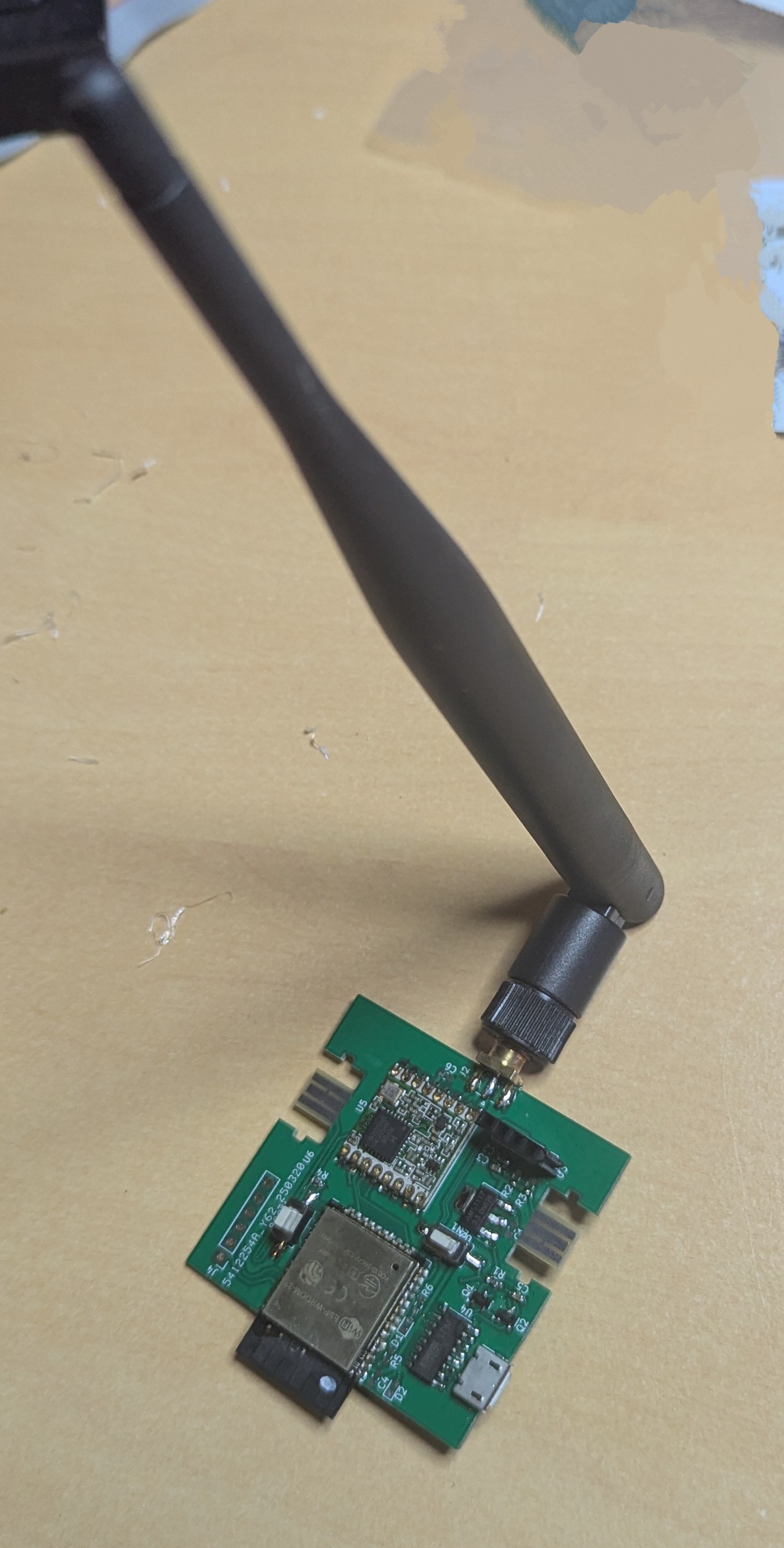
This project integrates an ESP32 microcontroller with LoRa communication and two Nunchuck connectors, enabling remote control and data transmission applications. The system is designed for long-range communication while leveraging the Wii Nunchuck controllers for user input.
| ESP32 Pin | LoRa Pin | Nunchuck 1 Pin | Nunchuck 2 Pin |
|---|---|---|---|
| 3.3V | VCC | VCC | VCC |
| GND | GND | GND | GND |
| GPIO5 | NSS | - | - |
| GPIO18 | SCK | - | - |
| GPIO19 | MISO | - | - |
| GPIO23 | MOSI | - | - |
| GPIO26 | DIO0 | - | - |
| GPIO21 | - | SDA (I²C 1) | - |
| GPIO22 | - | SCL (I²C 1) | - |
| GPIO25 | - | - | SDA (I²C 2) |
| GPIO33 | - | - | SCL (I²C 2) |
RadioHead or LoRa.h)Wire.h, ArduinoNunchuk.h)#include <Wire.h>
#include <ArduinoNunchuk.h>
#include <LoRa.h>
TwoWire I2C_1 = TwoWire(0);
TwoWire I2C_2 = TwoWire(1);
ArduinoNunchuk nunchuk1;
ArduinoNunchuk nunchuk2;
void setup() {
Serial.begin(115200);
I2C_1.begin(21, 22); // SDA1 = GPIO21, SCL1 = GPIO22
I2C_2.begin(25, 33); // SDA2 = GPIO25, SCL2 = GPIO33
nunchuk1.init(I2C_1);
nunchuk2.init(I2C_2);
LoRa.begin(915E6);
}
void loop() {
nunchuk1.update();
nunchuk2.update();Feel free to submit issues or pull requests for improvements and bug fixes.
Happy coding! 🚀
| Qty | Value | Footprint | References |
|---|---|---|---|
| 6 | C | Capacitor_SMD:C_0603_1608Metric | C1, C2, C3, C4, C5, C6 |
| 6 | R_Small | Resistor_SMD:R_0603_1608Metric | R1, R2, R3, R4, R5, R6 |
| 2 | BSS138 | Package_TO_SOT_SMD:SOT-23 | Q1, Q2 |
| 2 | LED | LED_SMD:LED_0603_1608Metric | D1, D2 |
| 2 | SW_Push | Button_Switch_SMD:SW_SPST_FSMSM | BOOT1, EN1 |
| 2 | ~ | nunchcuk:nunchuck | U3, U6 |
| 1 | AMS1117-3.3 | Package_TO_SOT_SMD:SOT-223-3_TabPin2 | U2 |
| 1 | CH340C | Package_SO:SOIC-16_3.9x9.9mm_P1.27mm | U4 |
| 1 | Conn_01x04 | Connector_PinHeader_2.54mm:PinHeader_1x04_P2.54mm_Vertical | J3 |
| 1 | Conn_01x06 | Connector_PinHeader_2.54mm:PinHeader_1x06_P2.54mm_Vertical | J4 |
| 1 | Conn_Coaxial | Connector_Coaxial:SMA_Samtec_SMA-J-P-H-ST-EM1_EdgeMount | J2 |
| 1 | ESP32-WROOM-32 | RF_Module:ESP32-WROOM-32 | U1 |
| 1 | RFM95W-868S2 | RF_Module:HOPERF_RFM9XW_SMD | U5 |
| 1 | USB_B_Micro | Connector_USB:USB_Micro-B_Amphenol_10118194_Horizontal | J1 |
rmingon/Falcon-Edge
A 3D-printable flying-wing airframe with a custom ESP32 flight computer—open hardware you can solder, screw together, and fly.


OpenLaundry/wifi-rfid-uhf-reader
Portable long range RFID uhf reader with WIFI based on esp32

rmingon/rs485-spy-injector
RS485 Spy is an open-source hardware tool for real-time monitoring, logging, and testing of RS-485 networks

rmingon/OverWire
Flash and debug STM32 microcontrollers over Wi-Fi. Enterprise-ready ESP32 SWD programming hardware and toolchain integration.


It measures 47.5 × 50.3 mm and has 2 copper layers, 1.6 mm thick.
28 parts, built around the CH340C, ESP32-WROOM-32, AMS1117-3.3 and RFM95W-868S2. The full list of its parts is on this page, with links to each part's symbol and footprint where PCBKit's library has them.
From the rmingon/esp32-lora repository on GitHub, at the commit this page was made from: the board is hardware/hardware.kicad_pcb and its schematic hardware/hardware.kicad_sch. PCBKit opens the board in the browser, with nothing to install.
Its repository states no licence, so its author keeps all rights: ask rmingon before reusing the design.