

2 layers40 × 78 mm
Hardware v2
rmingon/Falcon-Edge
A 3D-printable flying-wing airframe with a custom ESP32 flight computer—open hardware you can solder, screw together, and fly.
56 parts11

 rmingon/open-lora-com
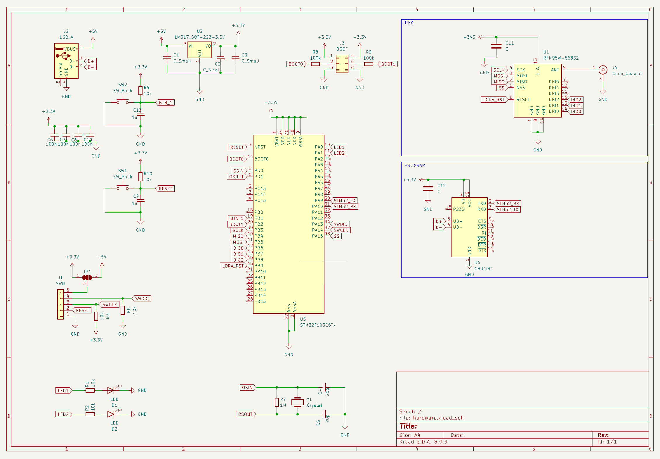
This project is a compact, embedded hardware system designed to securely transmit data over LoRa. Built around the STM32F103 microcontroller, this system supports real-time SHA encryption, flexible protocol configuration, and communication via a CH340 USB-to-UART interface.
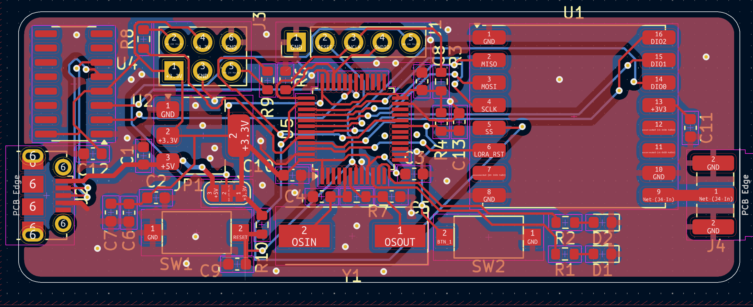
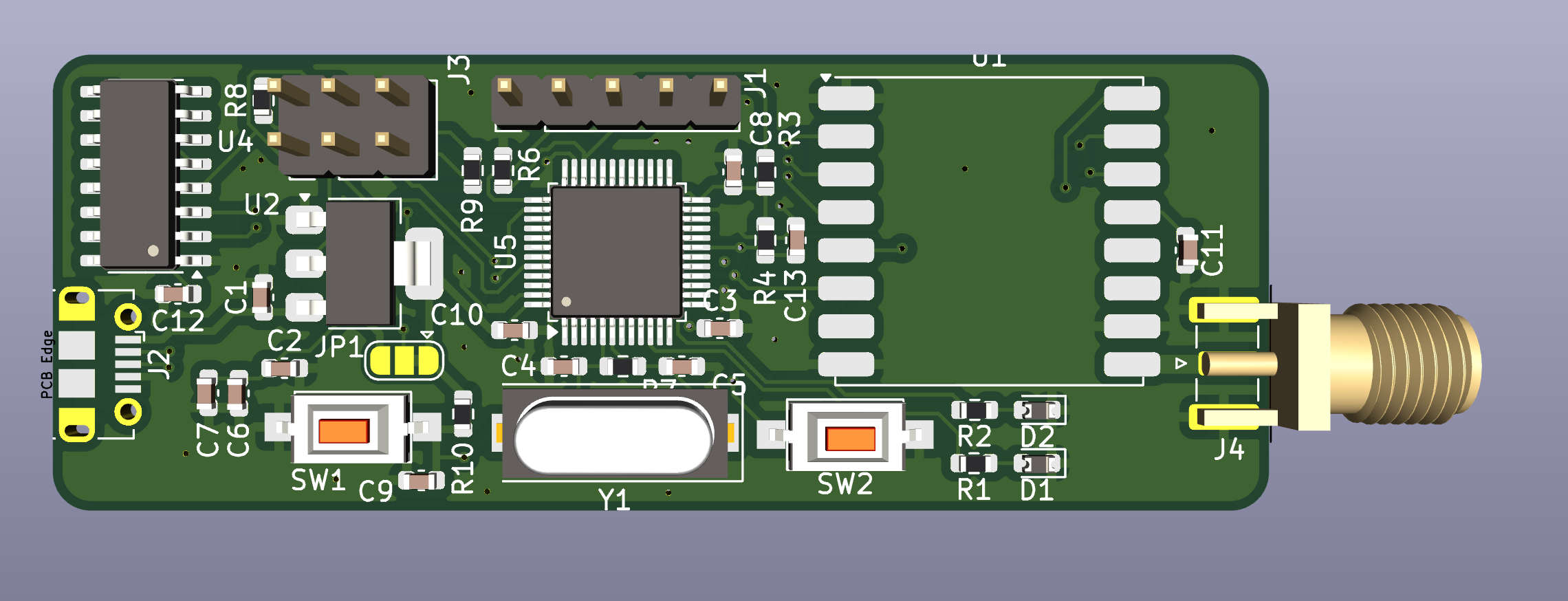
Open lora com is an open-source printed circuit board by rmingon, from the rmingon/open-lora-com repository on GitHub. It is a 2-layer board of 64 × 24 mm with 36 parts on 64 nets, routed with 397 tracks and 71 vias.
It is built around the CH340C and RFM95W-868S2. Its parts include 13 capacitors, 9 resistors, 4 ICs, 4 connectors and 2 diodes. It belongs with the radio and wireless and interfaces and adapters boards and the STM32 boards of this library.
This project is a compact, embedded hardware system designed to securely transmit data over LoRa. Built around the STM32F103 microcontroller, this system supports real-time SHA encryption, flexible protocol configuration, and communication via a CH340 USB-to-UART interface.
| Component | Description |
|---|---|
| U5 | STM32F103C8T6 - 32-bit ARM Cortex-M3 MCU |
| U1 | RFM95W LoRa module (868 MHz) |
| U4 | CH340C USB-UART bridge |
| U2 | LM317 3.3V voltage regulator |
| Y1 | 8 MHz crystal for MCU clock |
| J2 | USB Type-A input |
| J4 | SMA antenna connector |
The firmware handles:
A PC-side software GUI (in development) will provide:
This project is licensed under the MIT License — use it, modify it, and share it freely.
| Qty | Value | Footprint | References |
|---|---|---|---|
| 6 | 10k | Resistor_SMD:R_0603_1608Metric | R1, R2, R3, R4, R6, R10 |
| 4 | 100n | Capacitor_SMD:C_0603_1608Metric | C6, C7, C8, C10 |
| 3 | C_Small | Capacitor_SMD:C_0603_1608Metric | C1, C2, C3 |
| 2 | 100k | Resistor_SMD:R_0603_1608Metric | R8, R9 |
| 2 | 1u | Capacitor_SMD:C_0603_1608Metric | C9, C13 |
| 2 | 20p | Capacitor_SMD:C_0603_1608Metric | C4, C5 |
| 2 | C | Capacitor_SMD:C_0603_1608Metric | C11, C12 |
| 2 | LED | Diode_SMD:D_0603_1608Metric | D1, D2 |
| 2 | SW_Push | Button_Switch_SMD:SW_SPST_CK_RS282G05A3 | SW1, SW2 |
| 1 | 1M | Resistor_SMD:R_0603_1608Metric | R7 |
| 1 | BOOT | Connector_PinHeader_2.54mm:PinHeader_2x03_P2.54mm_Vertical | J3 |
| 1 | CH340C | Package_SO:SOIC-16_3.9x9.9mm_P1.27mm | U4 |
| 1 | Conn_Coaxial | Connector_Coaxial:SMA_Samtec_SMA-J-P-H-ST-EM1_EdgeMount | J4 |
| 1 | Crystal | Crystal:Crystal_SMD_HC49-SD | Y1 |
| 1 | LM317_SOT-223-3.3V | Package_TO_SOT_SMD:SOT-223-3_TabPin2 | U2 |
| 1 | RFM95W-868S2 | RF_Module:HOPERF_RFM9XW_SMD | U1 |
| 1 | STM32F103C6Tx | Package_QFP:LQFP-48_7x7mm_P0.5mm | U5 |
| 1 | SWD | Connector_PinHeader_2.54mm:PinHeader_1x05_P2.54mm_Vertical | J1 |
| 1 | SolderJumper_3_Bridged12 | Jumper:SolderJumper-3_P1.3mm_Bridged12_RoundedPad1.0x1.5mm | JP1 |
| 1 | USB_A | Connector_USB:USB_Micro-B_Molex-105017-0001 | J2 |
rmingon/Falcon-Edge
A 3D-printable flying-wing airframe with a custom ESP32 flight computer—open hardware you can solder, screw together, and fly.


dridri/bcflight
Raspberry Pi based drone flight controller and remote control


cernohorsky/LoRa-Node
Simple LoRa Node based on Arduino Pro mini with RFM95W module and PCB antenna.
It measures 64 × 24 mm and has 2 copper layers, 1.6 mm thick.
36 parts, built around the CH340C and RFM95W-868S2. The full list of its parts is on this page, with links to each part's symbol and footprint where PCBKit's library has them.
From the rmingon/open-lora-com repository on GitHub, at the commit this page was made from: the board is hardware/hardware.kicad_pcb and its schematic hardware/hardware.kicad_sch. PCBKit opens the board in the browser, with nothing to install.
Its repository states no licence, so its author keeps all rights: ask rmingon before reusing the design.