

6 layers200 × 200 mm

 rmingon/Cogless4
Open-source single-chip FOC ESC. One RISC-V MCU (CH32M007) with integrated gate driver, current-sense PGA and regulators drives a 4S / 30V power stage on a 45×40mm 4-layer board. KiCad sources under CERN-OHL-P v2.
Cogless is an open-source printed circuit board by rmingon, from the rmingon/Cogless repository on GitHub. It is a 4-layer board of 45 × 40 mm with 55 parts on 35 nets, routed with 432 tracks and 283 vias.
It is built around the CH32M007G8R6 and AOD514. Its parts include 24 resistors, 15 capacitors, 6 transistors, 2 connectors and 1 IC. It belongs with the robots and motor control boards of this library.
A single-chip, open-source brushless ESC built around the WCH CH32M007.
One RISC-V motor-control SoC, six MOSFETs, a handful of passives. Every design file public.







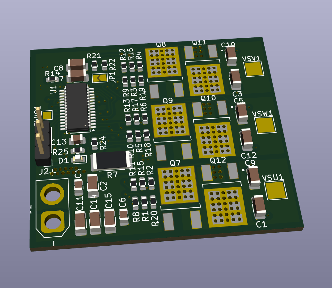
Most hobby ESCs are black boxes: closed firmware, undocumented hardware, and a microcontroller, gate driver and op-amps spread over a dozen chips. Cogless takes the opposite approach.
The WCH CH32M007G8R6 integrates on a single die everything the brain of an ESC needs: a RISC-V core, a three-phase 48 V N+N gate pre-driver with bootstrap diodes, the high-voltage and logic regulators, a programmable-gain current amplifier, comparators wired to the PWM timer's emergency brake, and a 3 Msps ADC. The result is a complete motor controller with one IC, six MOSFETs and a few passives on a 45 × 40 mm board.
| Control | Sensorless six-step (trapezoidal) commutation, back-EMF sensing |
| Start-up | Automatic motor detection and tuning, stored in flash |
| Protection | Hardware over-current break, cycle-by-cycle current limit, voltage and thermal derating |
| Openness | KiCad sources, fabrication outputs and firmware, dual-licensed |
| Parameter | Value |
|---|---|
| Controller | WCH CH32M007G8R6, QingKe RISC-V, 48 MHz, 62 KB flash, 8 KB RAM, SSOP-28 |
| Gate driver | Integrated three-phase N+N pre-driver, bootstrap diodes, up to 48 V |
| Power stage | 6 × AOD514 (30 V, 46 A, 5.9 mΩ), DPAK, thermal via arrays |
| Supply | 2S to 4S LiPo (6 V to 16.8 V), XT30 connector |
| Regulation | Internal high-voltage LDO and 5 V logic LDO, no external regulator |
| Current sense | 2 mΩ 2512 shunt, Kelvin-routed differential pair, internal PGA (× 16) |
| Voltage sense | Three phase back-EMF dividers and one battery divider, 33 kΩ / 8.2 kΩ (≈ 25 V full scale) |
| Temperature | 10 kΩ B3500 NTC (Cantherm CMFA103J3500HANT) against the low-side MOSFETs |
| Control input | 3-pin header (5 V, GND, signal) |
| Debug | WCH 1-wire SDI (SWIO pad), WCH-LinkE |
| Indicator | Status LED |
| Board | 4 layers, 45 × 40 mm, KiCad 10 |
| Topic | Choice |
|---|---|
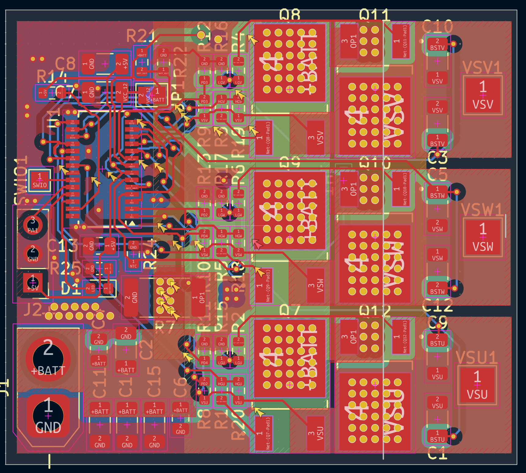
| Current sensing | The shunt is read differentially: both PGA inputs run as a Kelvin pair straight from the shunt pads, so gate-drive noise and power-trace drops stay out of the measurement. |
| Hardware over-current | The PGA output feeds an internal comparator wired to the timer's break input: the bridge shuts down without any software involvement. |
| Gate safety | All six MOSFETs have 100 kΩ gate pull-downs, the high sides referenced to their own phase node, so the bridge stays off while the driver powers up. |
| Sensorless and encoder-ready | The three phase dividers feed the ADC for back-EMF detection. The control header lands on an ADC and timer-capable pin, ready for an AS5600 or MT6701 encoder. |
| Supply jumper JP1 | Shorts VHV to VCC12V and bypasses the internal high-voltage regulator, which needs more than 18 V. JP1 must stay closed for every supported pack, 2S to 4S. It is bridged by default. |
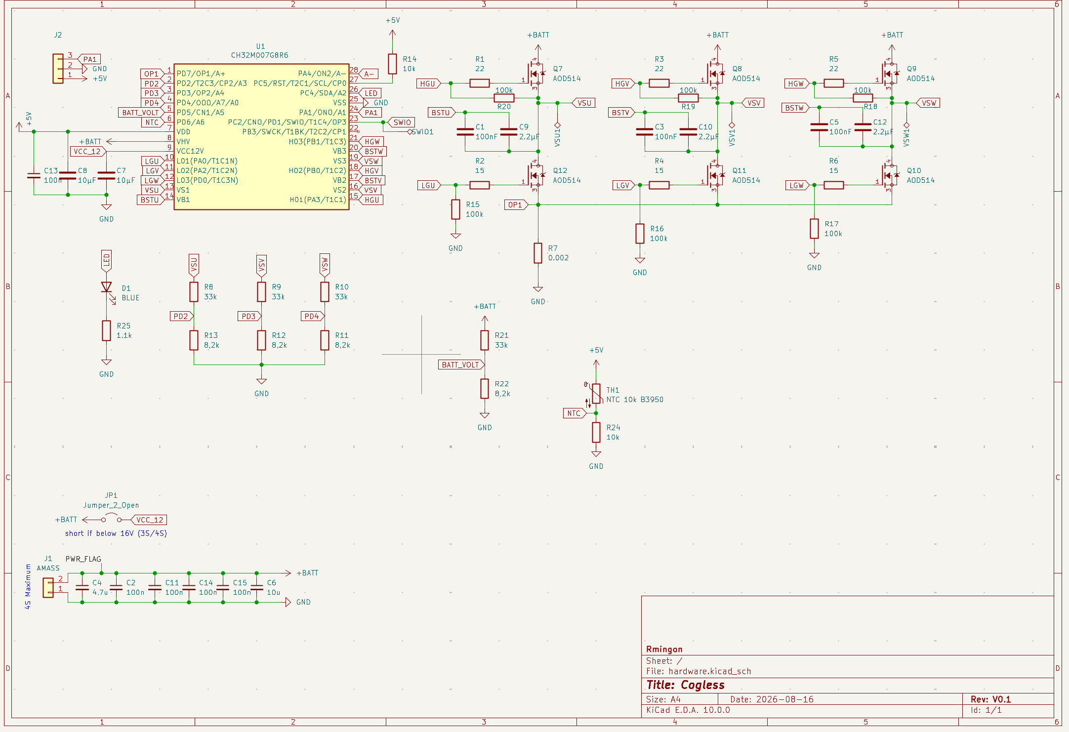
The full KiCad project (schematic, routed board) and the fabrication outputs (BOM, placement, netlist, Gerber archive) are in hardware/.
The firmware lives in firmware_DShot/ as a MounRiver Studio 2 project, with its own README covering the internals, the test modes and the bring-up notes.
| Feature | Description | Status |
|---|---|---|
| Six-step sensorless control | 48 kHz centre-aligned PWM, 400 ns dead time, closed loop on back-EMF zero crossings | Validated at 24 kHz, 48 kHz bench pending |
| Back-EMF sensing | Floating phase sampled in the PWM off-time, against ground | Validated |
| Current sensing | Single shunt, differential PGA, sampled inside the high-side pulse | Validated |
| Motor auto-tune | Start current, noise floor, open-loop acceleration, hand-off speed, closed-loop acceleration | Validated |
| Start-up and arming tones | The motor itself is used as a speaker | Validated |
| Servo PWM input | 1000 to 2000 µs on the control header | Implemented, bench validation pending |
| Load test | Power stage under a real propeller or vehicle load | In progress |
| DShot input, telemetry | Digital throttle protocol | Planned |
| Field-oriented control | Sinusoidal drive from the same hardware | Planned |
| Protection | Behaviour |
|---|---|
| Hardware over-current | Comparator to timer break, outputs off immediately |
| Software over-current | Fault after three consecutive samples above the limit |
| Current limiting | Cycle-by-cycle peak limit and slow fold-back |
| Speed ceiling | Duty backed off at the highest speed the sampling can follow |
| Under-voltage | Cell count detected at arming, fold-back then cut-off per cell |
| Over-temperature | Board temperature read every 100 ms, derating from 80 °C, cut-off at 100 °C |
| Loss of signal | Throttle failsafe after 100 ms without a valid pulse |
| Desynchronisation and stall | Outputs off, automatic restart at zero throttle |
| Watchdog | Independent watchdog, 100 ms |
| Limitation | Detail |
|---|---|
| Speed ceiling | About 80 000 eRPM at 48 kHz (≈ 11 400 rpm on a 14-pole motor), duty limited to about 83 % |
| Load validation | Full-power behaviour under a propeller is still being characterised |
| Step | Action |
|---|---|
| 1 | Order the board from the files in hardware/production/, or build it from the KiCad sources. |
| 2 | Check that JP1 is closed. |
| 3 | Open firmware_DShot/ in MounRiver Studio 2, build, and flash through a WCH-LinkE on SWIO, GND and 5 V. |
| 4 | First power-up on a current-limited supply, motor fixed, no propeller. The ESC beeps, then tunes itself to the motor. |
| 5 | Set the throttle source and limits in motor_config.h. |
| Path | Content |
|---|---|
hardware/ | KiCad 10 project: schematic, PCB |
hardware/production/ | Fabrication outputs: BOM, placement, netlist, Gerber archive |
firmware_DShot/ | Firmware, MounRiver Studio 2 project |
firmware_DShot/User/ | Cogless firmware sources |
LICENSE-HARDWARE | CERN-OHL-S v2 |
LICENSE-FIRMWARE | GPL-3.0 |
LICENSE-COMMERCIAL.md | Commercial licensing |
The CH32M007 datasheet and reference manual are available from WCH.
Warning. This is a power-electronics project. LiPo batteries and spinning motors can cause fire and serious injury. Always start on a current-limited supply, keep propellers off during bring-up and auto-tune, and never leave a first power-up unattended. You build and use this design at your own risk.
Issues and pull requests are welcome: layout review, firmware improvements, bring-up reports, or photos of your build. If you spin a variant (higher-voltage MOSFETs, other connectors), open a discussion first: the goal is a family of small, hackable ESCs.
Because Cogless is dual-licensed, a contribution can only be merged if you agree that it may also be distributed under the commercial licence. You keep the copyright of your contribution.
Cogless is dual-licensed: open source under strong copyleft licences, or under a commercial licence.
| Part | Open-source licence |
|---|---|
Hardware: everything under hardware/ | CERN-OHL-S v2 |
| Firmware: the files written for Cogless, marked with the Cogless SPDX header | GPL-3.0-only |
| You want to | Licence |
|---|---|
| Use, study, modify, build or sell Cogless, and publish your modified design files and firmware under the same licences | Open source, free of charge |
| Ship a product based on Cogless without publishing your changes, or combine the firmware with proprietary code | Commercial licence |
Third-party files. The WCH SDK files in firmware_DShot/Core/, Peripheral/, Startup/, Debug/, and the system_ch32v00X.*, ch32v00X_it.* and ch32v00X_conf.h files in User/, are copyright Nanjing Qinheng Microelectronics (WCH) and remain under WCH's own terms. They are not covered by the Cogless licences.
Copyright © 2026 Ronan Mingon
| Qty | Value | Footprint | References |
|---|---|---|---|
| 6 | 100k | Resistor_SMD:R_0603_1608Metric | R15, R16, R17, R18, R19, R20 |
| 6 | AOD514 | AOD514:TRANS_AOD514 | Q7, Q8, Q9, Q10, Q11, Q12 |
| 4 | 100n | Capacitor_SMD:C_1206_3216Metric | C2, C11, C14, C15 |
| 4 | 33k | Resistor_SMD:R_0603_1608Metric | R8, R9, R10, R21 |
| 4 | 8,2k | Resistor_SMD:R_0603_1608Metric | R11, R12, R13, R22 |
| 3 | 100nF | Capacitor_SMD:C_1206_3216Metric | C1, C3, C5 |
| 3 | 15 | Resistor_SMD:R_0603_1608Metric | R2, R4, R6 |
| 3 | 2.2µF | Capacitor_SMD:C_1206_3216Metric | C9, C10, C12 |
| 3 | 22 | Resistor_SMD:R_0603_1608Metric | R1, R3, R5 |
| 3 | TestPoint_Alt | TestPoint:TestPoint_Pad_3.0x3.0mm | VSU1, VSV1, VSW1 |
| 2 | 10k | Resistor_SMD:R_0603_1608Metric | R14, R24 |
| 2 | 10µF | Capacitor_SMD:C_1206_3216Metric | C7, C8 |
| 1 | 0.002 | Resistor_SMD:R_2512_6332Metric | R7 |
| 1 | 1.1k | Resistor_SMD:R_0603_1608Metric | R25 |
| 1 | 100n | Capacitor_SMD:C_0805_2012Metric | C13 |
| 1 | 10u | Capacitor_SMD:C_0805_2012Metric | C6 |
| 1 | 4.7u | Capacitor_SMD:C_0805_2012Metric | C4 |
| 1 | AMASS | Connector_AMASS:AMASS_XT30U-F_1x02_P5.0mm_Vertical | J1 |
| 1 | BLUE | LED_SMD:LED_0603_1608Metric | D1 |
| 1 | CH32M007G8R6 | Package_SO:SSOP-28_3.9x9.9mm_P0.635mm | U1 |
| 1 | Conn_01x03 | Connector_PinHeader_2.54mm:PinHeader_1x03_P2.54mm_Vertical | J2 |
| 1 | Jumper_2_Open | Jumper:SolderJumper-2_P1.3mm_Open_TrianglePad1.0x1.5mm | JP1 |
| 1 | NTC 10k B3950 | Capacitor_SMD:C_0603_1608Metric | TH1 |
| 1 | TestPoint_Alt | TestPoint:TestPoint_Pad_1.5x1.5mm | SWIO1 |
It measures 45 × 40 mm and has 4 copper layers, 1.6 mm thick.
55 parts, built around the CH32M007G8R6 and AOD514. The full list of its parts is on this page, with links to each part's symbol and footprint where PCBKit's library has them.
From the rmingon/Cogless repository on GitHub, at the commit this page was made from: the board is hardware/hardware.kicad_pcb and its schematic hardware/hardware.kicad_sch. PCBKit opens the board in the browser, with nothing to install.
Its repository states no licence, so its author keeps all rights: ask rmingon before reusing the design.


oomlout/oomlout_oomp_project_bot_v_2

Fr4nkFletcher/ESP32-Marauder-Cheap-Yellow-Display
ESP32Marauder Cheap Yellow Display


opentac/opentac
OpenTac: open tools to design, fabricate, read and simulate flex-PCB tactile skins that sense normal and shear force, for any robot surface.

AlexeyInwerp/BoardRipper
Web-based PCB boardview viewer for board-level repair. 14 formats: BVR1/3, BRD, BDV, BDV ASC, FZ, GenCAD, Mentor Neutral, XZZ, TVW, Allegro v15-v18, Altium, KiCad, EAGLE.

Terrails/FW16-OCuLink
The schematic in itself is pretty simple. You only need to connect the TX and RX PCIe lanes to the correct pins of the OCuLink connector.