4 layers177 × 152.1 mm

 rjhelms/6502proto2
A prototyping board for experimenting with 6502 hardware and software design
6502protoboard is an open-source printed circuit board by rjhelms, from the rjhelms/6502proto repository on GitHub. It is a 2-layer board of 142.2 × 175.3 mm with 95 parts on 237 nets, routed with 1,402 tracks and 71 vias.
It is built around the 74HC573, 74HC00D and 74HC08D, with the L7805 and SB240 among its other parts. Its parts include 31 connectors, 18 capacitors, 11 resistors, 11 ICs and 3 diodes.


A prototyping board for experimenting with 6502 hardware and software design

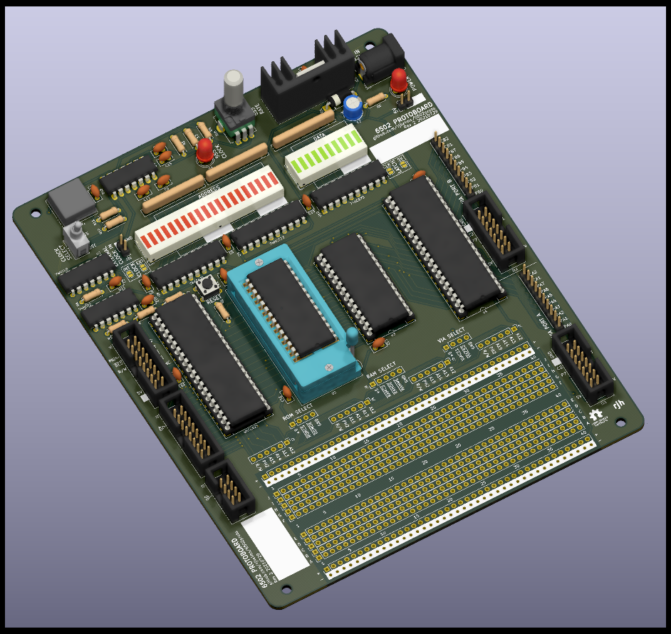
This board implements a minimal 6502 system, containing a 65C02 processor, a 65C22 Versatile Interface Adapter (VIA), a 32kB EEPROM and 32kB of SRAM.
This project would not have been possible without Garth Wilson's excellent 6502 Primer, which is eseential reading for anyone looking to get started with 6502 homebrew.
More to come - for now, refer to the interactive BOM.
In order to let the 6502 processor talk to other chips, any 6502 system requires some address decoding logic. The board has no address decoding built in; it is up to the builder to implement their chosen address decoding with the breadboard area.
Pads above the breadboard area provide access to the 4 highest bytes of the address bus, as well as the PH2 clock and R/W, and the relevant inputs for each of the on-board ICs.
The address decoding chapter of Garth Wilson's primer is well worth a read before deciding what to implement.
Some key considerations when choosing an address decoding scheme:
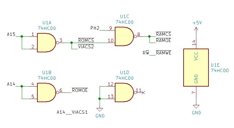
For a system only using the RAM, ROM, and VIA chips on board, satisfactory results can be achieved with a single 74HC00 quad NAND gate:
| Start | End | Device |
|---|---|---|
| $0000 | $7FFF | RAM |
| $8000 | $BFFF | VIA |
| $C000 | $FFFF | ROM |
With only 64kB of address space and 32kB of both RAM and ROM, at least some portion of one of these will need to be masked by the VIA or other devices. This logic masks the lower half of ROM, resulting in a system with 32kB of RAM and 16kB of ROM.
A similar addressing scheme with 16kB of RAM and 32kB of ROM can also be implemented with one 74HC00.
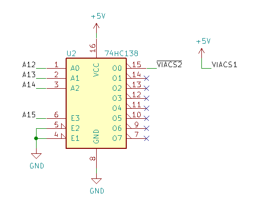
The minimal setup above works just fine for the chips on the protoboard, but doesn't leave any room for expanding the system any further. Also, while the VIA only needs 16 bytes of address space, the above setup allocates a whole 16kB to it!
By using a 74HC138 line decoder, that 16kB can be split into 8 2kB segments, each addressed by one output.
| Start | End | Device |
|---|---|---|
| $0000 | $7FFF | RAM |
| $8000 | $87FF | (VIA) '138 output 0 |
| ... | ||
| $B800 | $BFFF | '138 output 7 |
| $C000 | $FFFF | ROM |
| Pin | Signal | Pin | Signal |
|---|---|---|---|
| 1 | PH2 | 2 | PH2 |
| 3 | RESET | 4 | RDY |
| 5 | R/W | 6 | IRQ |
| 7 | unused | 8 | NMI |
| 9 | unused | 10 | SYNC |
| 11 | unused | 12 | BE |
| 13 | 5V | 14 | 5V |
| 15 | GND | 16 | GND |
| Pin | Signal | Pin | Signal |
|---|---|---|---|
| 1 | A0 | 2 | A1 |
| 3 | A2 | 4 | A3 |
| 5 | A4 | 6 | A5 |
| 7 | A6 | 8 | A7 |
| 9 | A8 | 10 | A9 |
| 11 | A10 | 12 | A11 |
| 13 | A12 | 14 | A13 |
| 15 | A14 | 16 | A15 |
| Pin | Signal | Pin | Signal |
|---|---|---|---|
| 1 | D0 | 2 | D1 |
| 3 | D2 | 4 | D3 |
| 5 | D4 | 6 | D5 |
| 7 | D6 | 8 | D7 |
| Pin | Signal | Pin | Signal |
|---|---|---|---|
| 1 | 5V | 2 | 5V |
| 3 | PA0 | 4 | PA1 |
| 5 | PA2 | 6 | PA3 |
| 7 | PA4 | 8 | PA5 |
| 9 | PA6 | 10 | PA7 |
| 11 | CA1 | 12 | CA2 |
| 13 | GND | 14 | GND |
| Qty | Value | Footprint | References |
|---|---|---|---|
| 14 | Conn_01x40 | Connector_PinHeader_2.54mm:PinHeader_1x40_P2.54mm_Vertical | J15, J16, J17, J18, J19, J20, J21, J22, J23, J24, J25, J26, J27, J28 |
| 13 | 100n | Capacitor_THT:C_Disc_D5.0mm_W2.5mm_P2.50mm | C1, C4, C5, C6, C7, C8, C9, C10, C11, C12, C13, C14, C18 |
| 6 | 1K | Resistor_THT:R_Axial_DIN0207_L6.3mm_D2.5mm_P7.62mm_Horizontal | R6, R7, R8, R9, R10, R11 |
| 4 | 3K3 | Resistor_THT:R_Axial_DIN0207_L6.3mm_D2.5mm_P7.62mm_Horizontal | R2, R3, R4, R5 |
| 4 | Conn_01x05 | Connector_PinHeader_2.54mm:PinHeader_1x06_P2.54mm_Vertical | J2, J4, J5, J7 |
| 4 | MountingHole | MountingHole:MountingHole_3.2mm_M3 | H1, H2, H3, H4 |
| 3 | 1K | Resistor_THT:R_Array_SIP9 | RN1, RN2, RN3 |
| 3 | 74HC573 | Package_DIP:DIP-20_W7.62mm | U8, U9, U10 |
| 2 | 10n | Capacitor_THT:C_Disc_D5.0mm_W2.5mm_P2.50mm | C15, C17 |
| 2 | Conn_01x02 | Connector_PinHeader_2.54mm:PinHeader_1x02_P2.54mm_Vertical | J30, J31 |
| 2 | Conn_01x04 | Connector_PinHeader_2.54mm:PinHeader_1x04_P2.54mm_Vertical | J8, J10 |
| 2 | Conn_01x10 | Connector_PinHeader_2.54mm:PinHeader_1x10_P2.54mm_Vertical | J13, J14 |
| 2 | Conn_02x07_Odd_Even | Connector_IDC:IDC-Header_2x07_P2.54mm_Vertical | J11, J12 |
| 2 | Conn_02x08_Odd_Even | Connector_IDC:IDC-Header_2x08_P2.54mm_Vertical | J1, J6 |
| 2 | DC-10EWA | Display:HDSP-4830 | BAR1, BAR2 |
| 2 | LED | LED_THT:LED_D5.0mm | D2, D3 |
| 2 | Logo_Open_Hardware_Small | Symbol:OSHW-Logo_5.7x6mm_SilkScreen | LOGO1, LOGO1 |
| 1 | 100u 25V | Capacitor_THT:CP_Radial_D6.3mm_P2.50mm | C2 |
| 1 | 1K8 | Resistor_THT:R_Axial_DIN0207_L6.3mm_D2.5mm_P7.62mm_Horizontal | R1 |
| 1 | 1MHz | Oscillator:Oscillator_DIP-8 | X1 |
| 1 | 1u | Capacitor_THT:C_Disc_D5.0mm_W2.5mm_P2.50mm | C16 |
| 1 | 28C256 | Socket:DIP_Socket-28_W11.9_W12.7_W15.24_W17.78_W18.5_3M_228-1277-00-0602J | U2 |
| 1 | 330n | Capacitor_THT:C_Disc_D5.0mm_W2.5mm_P2.50mm | C3 |
| 1 | 556 | Package_DIP:DIP-14_W7.62mm_LongPads | U6 |
| 1 | 62256 | Package_DIP:DIP-28_W15.24mm_Socket_LongPads | U3 |
| 1 | 74HC00 | Package_DIP:DIP-14_W7.62mm | U7 |
| 1 | 74HC08 | Package_DIP:DIP-14_W7.62mm | U11 |
| 1 | B1M | Potentiometer_Custom:Potentiometer_Alpha_RD901F-40-00D_Single_Vertical_Centered | RV1 |
| 1 | Barrel_Jack_Switch | Connector_BarrelJack:BarrelJack_Wuerth_6941xx301002 | J29 |
| 1 | Conn_01x04 | Connector_PinHeader_2.54mm:PinHeader_1x05_P2.54mm_Vertical | J9 |
| 1 | Conn_02x04_Odd_Even | Connector_IDC:IDC-Header_2x04_P2.54mm_Vertical | J3 |
| 1 | DC-10GWA | Display:HDSP-4850 | BAR3 |
| 1 | Heatsink | Heatsinks_Custom:Heatsink_Assman_V4330N | HS1 |
| 1 | L7805 | Package_TO_SOT_THT:TO-220-3_Vertical | U5 |
| 1 | SB240 | Diode_THT:D_DO-15_P10.16mm_Horizontal | D1 |
| 1 | SW_Push | Button_THT_Custom:SW_TH_Tactile_Omron_B3F-10xx_Common_Pins | SW1 |
| 1 | SW_SPDT | Switches_THT_Custom:SW_SPDT_E-Switch_200MSP1xM2 | SW2 |
| 1 | SolderJumper_2_Bridged | Jumper:SolderJumper-2_P1.3mm_Open_RoundedPad1.0x1.5mm | JP2 |
| 1 | SolderJumper_2_Open | Jumper:SolderJumper-2_P1.3mm_Bridged_RoundedPad1.0x1.5mm | JP1 |
| 1 | SolderJumper_Bridged | Jumper:SolderJumper-2_P1.3mm_Bridged_RoundedPad1.0x1.5mm | JP3 |
| 1 | SolderJumper_Open | Jumper:SolderJumper-2_P1.3mm_Open_RoundedPad1.0x1.5mm | JP4 |
| 1 | W65C02S | Package_DIP:DIP-40_W15.24mm_Socket_LongPads | U1 |
| 1 | W65C22S | Package_DIP:DIP-40_W15.24mm_Socket_LongPads | U4 |


stonedDiscord/Automatenplatinen
Reverse engineerte Hardware aus deutschen Spielautomaten.


punkfab/pcb-corpus
235 real KiCad boards from open-source hardware repositories, prepared as a placement and routing benchmark


stonedDiscord/servicetastatur
Klon der blauen Servicetastatur für Merkur Profitech 3000 Geräte
It measures 142.2 × 175.3 mm and has 2 copper layers, 1.6 mm thick.
95 parts, built around the 74HC573, 74HC00D, 74HC08D and L7805. The full list of its parts is on this page, with links to each part's symbol and footprint where PCBKit's library has them.
From the rjhelms/6502proto repository on GitHub, at the commit this page was made from: the board is 6502protoboard.kicad_pcb. PCBKit opens the board in the browser, with nothing to install.
Its repository states no licence, so its author keeps all rights: ask rjhelms before reusing the design.