
2 layers327.9 × 139 mm
Coco2
baldengineer/bit-preserve
Project for capturing vintage, classic, aka old computer schematics in KiCad.
147 parts446

 rjafari44/555-Timer-PCB
PCB for running a 555 timer IC in astable mode to drive an LED.
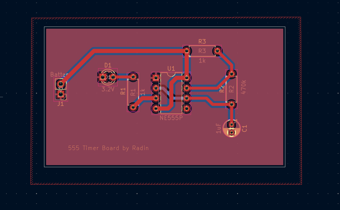
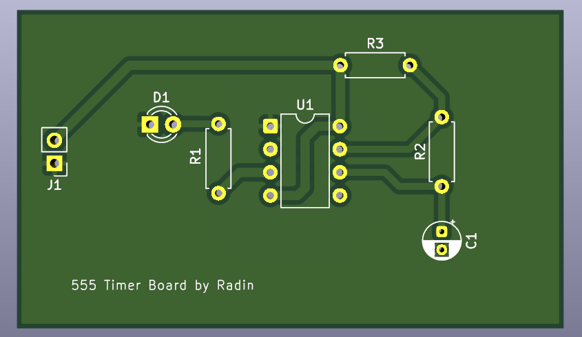
555 timer is an open-source printed circuit board by rjafari44, from the rjafari44/555-Timer-PCB repository on GitHub, published under the MIT licence. It is a 2-layer board of 60 × 35 mm with 7 parts on 7 nets, routed with 28 tracks and 0 vias.
It is built around the NE555P. Its parts include 3 resistors, 1 capacitor, 1 IC, 1 diode and 1 connector.
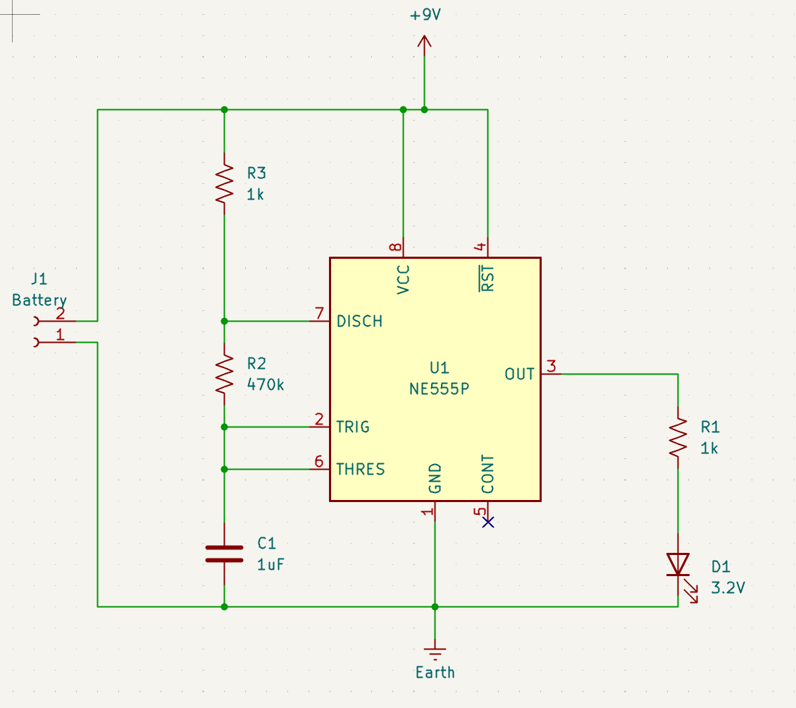
This PCB is a simple 555 timer circuit configured in astable mode, designed to blink an LED. It is powered by a 9V battery and includes a single LED with a current-limiting resistor.
This was a project done under IEEE at UC Irvine. The PCB was designed using KiCad.
Key features:
| Pin | Connection |
|---|---|
| VCC | Positive battery terminal (+9V) |
| GND | Negative battery terminal |
| DISCH | Connected through R3 (1kΩ) to VCC node |
| TRIG | Connected to R2 (470kΩ) from DISCH and 1µF capacitor to GND |
| THRES | Connected to TRIG and 1µF capacitor to GND |
| OUT | LED in series with R1 (1kΩ) to GND |
| RESET | Tied to VCC node (battery positive) |
| CV | Disconnected |
The LED includes a built-in 1kΩ current-limiting resistor.
Note: The battery connector is where you connect the 9V battery; observe LED polarity.
For a 555 timer in astable mode:
T_high = 0.693 * (R2 + R3) * C
T_low  = 0.693 * R2 * C
T_total = T_high + T_low = 0.693 * (R3 + 2*R2) * C
f = 1 / T_total
Duty cycle = T_high / T_total
Using component values:
Step 1: Total period
T_total = 0.693 * (R3 + 2*R2) * C
T_total = 0.693 * (1,000 + 2*470,000) * 0.000001
T_total ≈ 0.651 seconds
Step 2: Frequency
f = 1 / T_total ≈ 1 / 0.651 ≈ 1.54 HzStep 3: Duty cycle
T_high = 0.693 * (R2 + R3) * C
T_high = 0.693 * (470,000 + 1,000) * 0.000001 ≈ 0.326 s
Duty cycle ≈ T_high / T_total ≈ 0.326 / 0.651 ≈ 50%
R1 (LED resistor) does not affect timing.
| Qty | Value | Footprint | References |
|---|---|---|---|
| 2 | 1k | Resistor_THT:R_Axial_DIN0207_L6.3mm_D2.5mm_P7.62mm_Horizontal | R1, R3 |
| 1 | 1uF | Capacitor_THT:CP_Radial_D4.0mm_P2.00mm | C1 |
| 1 | 3.2V | LED_THT:LED_D3.0mm | D1 |
| 1 | 470k | Resistor_THT:R_Axial_DIN0207_L6.3mm_D2.5mm_P7.62mm_Horizontal | R2 |
| 1 | Battery | Connector_PinHeader_2.54mm:PinHeader_1x02_P2.54mm_Vertical | J1 |
| 1 | NE555P | Package_DIP:DIP-8_W7.62mm | U1 |
It measures 60 × 35 mm and has 2 copper layers, 1.6 mm thick.
7 parts, built around the NE555P. The full list of its parts is on this page, with links to each part's symbol and footprint where PCBKit's library has them.
From the rjafari44/555-Timer-PCB repository on GitHub, at the commit this page was made from: the board is kicad-files/555_timer.kicad_pcb and its schematic kicad-files/555_timer.kicad_sch. PCBKit opens the board in the browser, with nothing to install.
Its repository publishes it under the MIT licence: you may reuse it on that licence's terms (keep the author's notice, and for a copyleft licence share your changes alike).
baldengineer/bit-preserve
Project for capturing vintage, classic, aka old computer schematics in KiCad.

The-Invent0r/8-bit-Computer-PCB
These are the KiCAD files for my 8-Bit Computer.

DarcyJProjects/touchtone555
An open-source DIY, NE555-based analogue synthesizer - play notes with a stylus


benjiaomodular/SynthCard
I designed this project with the help of PCBWay. You can get a copy of these cards through the PCBWay Shared Projects page.

fortinsylvain/MyCpu
Home brew CPU Hardware with 1-bit ALU implementation using 74LSxx, a micro-code and assembler coded in C#.

hackup/C128Diag
Replica of the Commodore C128 Diagnostic Test cartridge Assy No. 325093-01.