4 layers35.6 × 39.4 mm
 rixth/5x7_Controller
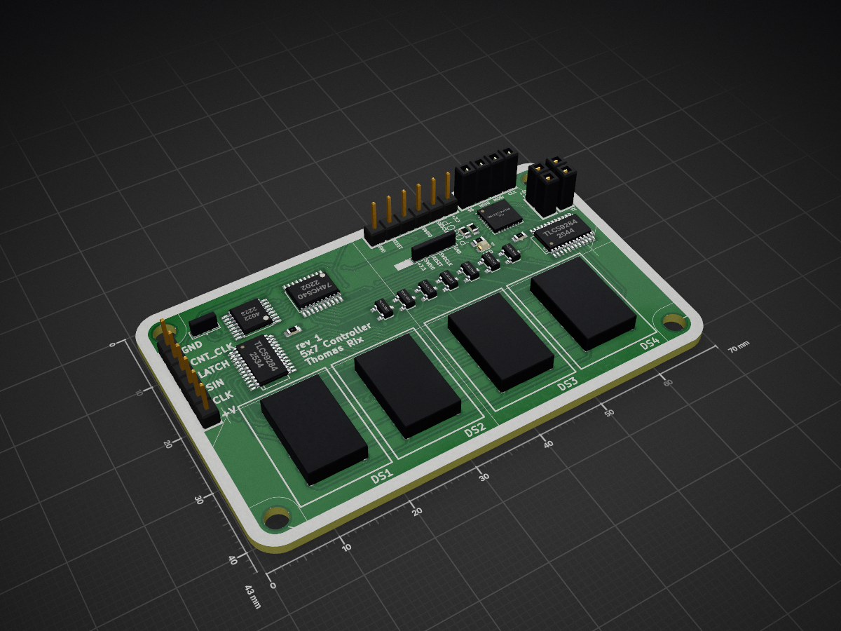
A controller for four 5x7 LED matrices
5x7 Controller is an open-source printed circuit board by rixth, from the rixth/5x7_Controller repository on GitHub. It is a 2-layer board of 70 × 43 mm with 31 parts on 64 nets, routed with 680 tracks and 79 vias.
It is built around the MKL02Z32VFM4, 74HC540D and TLC59284DBQ, with the IRLML5203 and VAOM-C07573G9-BW/32 among its other parts. Its parts include 7 transistors, 7 connectors, 5 ICs, 3 resistors and 2 capacitors. It belongs with the NXP (LPC, Kinetis, i.MX RT) boards of this library.


This is a project that provides hardware & firmware for a small (43x70mm) board that contains four 5x7 row-anode LED matrices.
This display is drawn row-by-row. The row to be drawn is selected by the counter, which feeds it output through an inverting-buffer, then out to the P-channel mosfets. The columns are selected by the TLC59284 which are essentially shift registers that can sink considerable (configurable) current, so you can avoid having many current limiting resistors for the LEDs.
The Kinetis MCU will be responsible for drawing the display, and receiving commands from the main controller. I have exposed the MCU's i2c, SPI and UART lines to headers.
The raw inputs for the row/column selection have also been broken out to the left side of the board - 4 pins are required (shift clk, in, latch + counter clk). This can be reduced by 1 if a solder bridge is used to tie the clock of the counter to the latch of the shift register.
The software is still in the planning phases, but the rough plan is to use a slim RTOS like AtomThreads to both keep the display refeshed and take input from the host controller over i2c, SPI or serial.
The MCU will have an ASCII character set preloaded - but the command set will also allow the host to toggle single LEDs, rows and columns.
| Qty | Value | Footprint | References |
|---|---|---|---|
| 7 | IRLML5203 | w_smd_trans:sot23 | Q1, Q2, Q3, Q4, Q5, Q6, Q7 |
| 4 | VAOM-C07573G9-BW/32 | 5x7Controller:VAOM-A07573G9 | DS1, DS2, DS3, DS4 |
| 2 | 2.7K | w_smd_resistors:r_0603 | R1, R2 |
| 2 | TLC59284 | w_smd_dil:ssop-24 | U2, U3 |
| 1 | aurai:DP7043 | ||
| 1 | 0.1uF | w_smd_cap:c_0603 | C1 |
| 1 | 10uF | w_smd_cap:c_0603 | C2 |
| 1 | 220 | w_smd_resistors:r_0603 | R3 |
| 1 | 4022 | w_smd_dil:tssop-16 | U1 |
| 1 | 74HC540 | w_smd_dil:tssop-20 | U4 |
| 1 | CNT_CLK_SEL | w_details:3-way_bridge_0603 | J1 |
| 1 | HEADER_6 | w_pin_strip:pin_strip_6 | J2 |
| 1 | I2C | w_pin_strip:pin_socket_2 | J5 |
| 1 | LED | w_smd_leds:Led_0603 | LD1 |
| 1 | MKL02Z32VFM4 | Housings_DFN_QFN:QFN-32-1EP_5x5mm_Pitch0.5mm | U5 |
| 1 | PCB_DP_RECTANGLE-43X70 | dp_devices:dp_devices-DP7043_V1 | PCB1 |
| 1 | POGOPROG | 5x7Controller:POGOPROG-CONN-OH-SMALLERVIAS | J4 |
| 1 | PROGRAMMING | w_pin_strip:pin_strip_6 | J7 |
| 1 | SPI | w_pin_strip:pin_socket_4 | J3 |
| 1 | UART | w_pin_strip:pin_socket_2 | J6 |
It measures 70 × 43 mm and has 2 copper layers, 1.6 mm thick.
31 parts, built around the MKL02Z32VFM4, 74HC540D, TLC59284DBQ and IRLML5203. The full list of its parts is on this page, with links to each part's symbol and footprint where PCBKit's library has them.
From the rixth/5x7_Controller repository on GitHub, at the commit this page was made from: the board is hardware/5x7Controller.kicad_pcb. PCBKit opens the board in the browser, with nothing to install.
Its repository states no licence, so its author keeps all rights: ask rixth before reusing the design.

tmarhguy/tomato
A functional 32-bit computer built from scratch in a dorm; implemented on FPGA, Kicad, browser simulation

dkjonas/WildWillyR5Hardware
Schematic and board layout for the R5 version of my robot.


michAtEl/Bonsai-Modellcomputer
Es gibt auch eine Simulation des Lerncomputers (https://bonsai.pinyto.de/), die im digitalen Informatik-Schulbuch http://inf-schule.de verwendet wird.