
2 layers31.7 × 68.3 mm
MainPCB
rivertechlabs/suspendedsedimentsensor
:ocean: 3D-printed, open-source suspended sediment sensor for river network monitoring (prototype 3.0)
23 parts12AGPL-3.0
:ocean: 3D-printed, open-source suspended sediment sensor for river network monitoring (prototype 3.0)
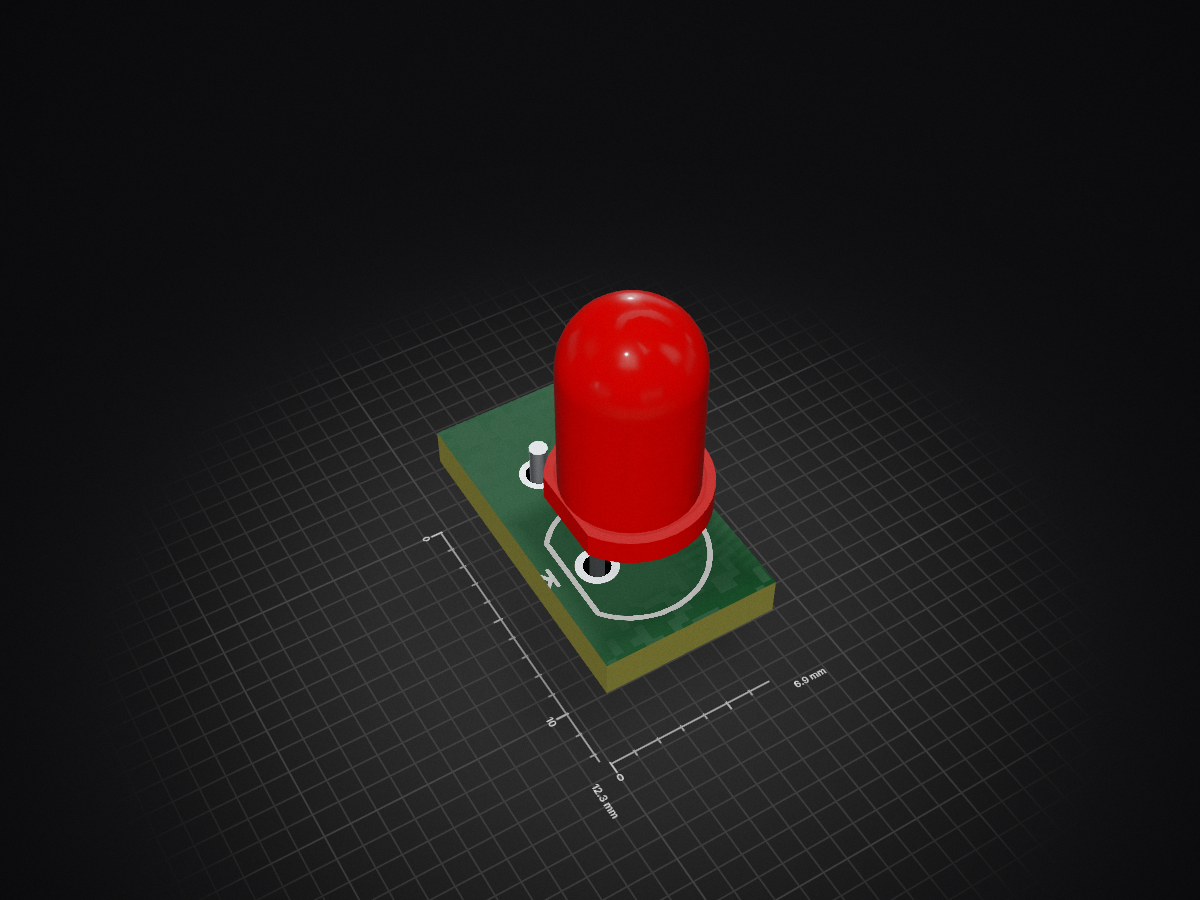
IRDiode is an open-source printed circuit board by rivertechlabs, from the rivertechlabs/suspendedsedimentsensor repository on GitHub, published under the AGPL-3.0 licence. It is a 2-layer board of 6.9 × 12.3 mm with 2 parts on 2 nets, routed with 5 tracks and 0 vias.
It is built around the TSHG6200. Its parts include 1 diode and 1 connector. It belongs with the sensors and measurement boards of this library.
This sensor is prototype 3.0 (or "version Ötz-T"). The previous prototype 2.0 (or "first version") is found in this repo (new repo because I consider the two versions different enough).
This sensor was published in HardwareX! Read Ötz-T: 3D-printed open-source turbidity sensor with Arduino shield for suspended sediment monitoring.
Improvements on this version:
A 3D-printed, open-source suspended sediment sensor for river network monitoring.
This repo is dedicated to the open-source turbidity sensor. More info can be found here:
This repo contains several items to build the current prototype of the open-source turbidity sensor including:
There are two codes in the Code folder: main.ino and set_time.ino. Please follow the instructions in set time.ino about changing the date in the program. After the program has flashed, every time the Arduino restarts (disconnect and reconnect to power) it will restart the RTC time to the original compile time of the set time.ino program. To mitigate this issue, the next program, main.ino, can be immediately flashed without disconnecting power or set time.ino can be re-flashed after commenting-out line 79 (“setPCF85263();”). Follow by flashing main.ino onto the Arduino. Please note that additional libraries may need to be downloaded and added to your library (e.g. the MS5803-05 external library). The main.ino program was written to take a measurement every hour (one measurement is an average of 15 measurements) to conserve battery, but this can be changed in the code if you require higher temporal resolution to capture larger variability e.g. from flushing of sediment from a dam.
Here you will find the printer files (.gcode) and the PrusaSlicer files (.3mf). The CAD files were exported as .stp and imported into the PrusaSlicer program (free). See the .3mf files to understand the settings we used in PrusaSlicer for optimal printing. The main settings were:
The .3mf files were exported as .gcode files and then printed on a Prusa I3 Mk3 and/or Mk3S Filament Printer.
We have provided the Gerber files to directly order the PCBs. Alternatively, the .PcbDoc and .SchDoc files can be opened in Altium (the eductional license can be obtained for free) where you can export your own Gerber files. Finally, the schematic and PCB files were also provided as KiCad files so that they can be viewed and edited without Altium.
In this folder we have the original CAD files (as STEP) so that they can be downloaded and adjusted for your project.
For questions, please email me at droujko@ifu.baug.ethz.ch or @rivertechjess on Twitter :bird:
| Qty | Value | Footprint | References |
|---|---|---|---|
| 1 | 61900211121 | Vault:61900211121 | P1 |
| 1 | TSHG6200 | Vault:Type 5mm | LED1 |
It measures 6.9 × 12.3 mm and has 2 copper layers, 1.6 mm thick.
2 parts, built around the TSHG6200. The full list of its parts is on this page, with links to each part's symbol and footprint where PCBKit's library has them.
From the rivertechlabs/suspendedsedimentsensor repository on GitHub, at the commit this page was made from: the board is PCB/IRDiode/IRDiode.kicad_pcb and its schematic PCB/IRDiode/IR_Diode_PCB.kicad_sch. PCBKit opens the board in the browser, with nothing to install.
Its repository publishes it under the AGPL-3.0 licence: you may reuse it on that licence's terms (keep the author's notice, and for a copyleft licence share your changes alike).
rivertechlabs/suspendedsedimentsensor
:ocean: 3D-printed, open-source suspended sediment sensor for river network monitoring (prototype 3.0)

rivertechlabs/suspendedsedimentsensor
:ocean: 3D-printed, open-source suspended sediment sensor for river network monitoring (prototype 3.0)

rivertechlabs/suspendedsedimentsensor
:ocean: 3D-printed, open-source suspended sediment sensor for river network monitoring (prototype 3.0)


hzeller/rpi-rgb-led-matrix
Controlling up to three chains of 64x64, 32x32, 16x32 or similar RGB LED displays using Raspberry Pi GPIO


adamws/kicad-kbplacer
KiCad plugin for automatic keyboard's key placement and routing

Luos-io/luos_engine
Open-source and real-time orchestrator for cyber-physical-systems, to easily design, test and deploy embedded applications and digital twins.

NVNTLabs/switch2-SDEX2M2
Micro SD Express to M.2 NVME Adapter for Nintendo Switch 2

BlueSCSI/BlueSCSI-v2
BlueSCSI v2/Ultra - an open source, open hardware, SCSI emulator using the Pi Pico PR2040 and Pico 2 RP2350

ohmtech-rdi/eurorack-blocks
Software to Hardware Prototyping for Eurorack using C++, Max/Gen~ or Faust