2 layers
Encoder
byrantech/laptop
anyon_e, a highly integrated, high end, open source laptop. Attempt the impossible.
7 parts4.3kMIT
 rishikrrontala-bot/patchline-bench
Nonclinical sensing bench prototype with local synthetic signal inference and an exploded-view observatory. Built by Rishik Rontala.
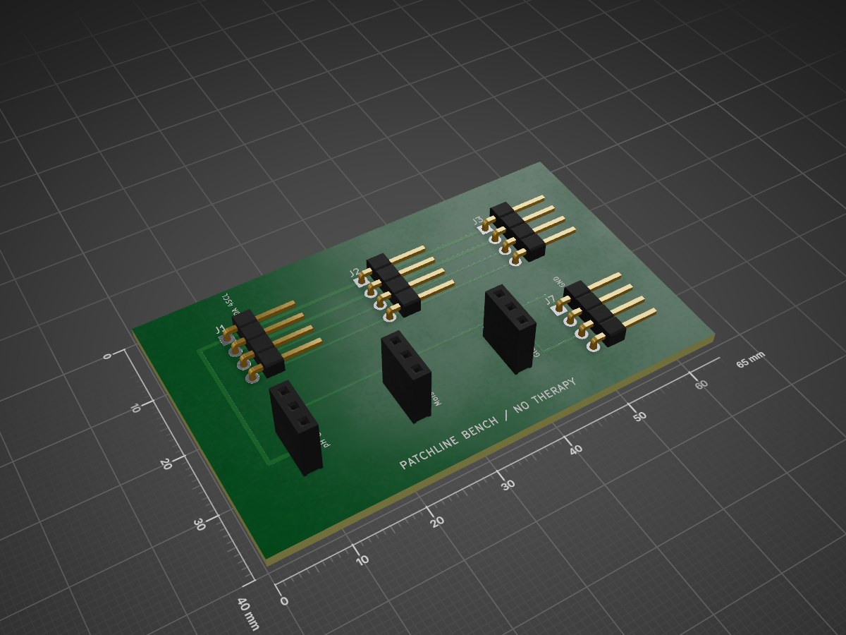
Patchline bench is an open-source printed circuit board by rishikrrontala-bot, from the rishikrrontala-bot/patchline-bench repository on GitHub. It is a 2-layer board of 65 × 40 mm with 7 parts on 7 nets, routed with 31 tracks and 0 vias.
Built by Rishik Rontala. A nonclinical sensing and signal-review prototype, kept separate from prior Patchline hackathon editions.
Run npm start, then open http://127.0.0.1:8790. Generate a reproducible steady, coordinated-shift or sensor-fault window. Inspect four charts and local model likelihoods; review an eligible synthetic window and log a virtual rehearsal. Import JSON locally or explicitly choose a USB serial port in a compatible browser. Bench and imported windows are always held. No hardware actuation or therapeutic dose exists.
The local classifier was trained from scratch on 1,200 simulated runs, selected using 300 validation runs, and evaluated on 300 independent test runs. Accuracy 89.7%, macro F1 89.4%. It missed 31 of 100 injected sensor faults; these metrics do not establish infection detection, medical benefit, or generalization to real sensors. A separate quality gate flags missing/held signals and prevents rehearsal for estimated faults or low confidence. Its review threshold is an explicit demo policy, not a clinical threshold.
npm test runs 35 independent software tests. python3 tools/board.py produces the passive PCB draft, netlist and drawing with layer-aware connectivity checks. node tools/generate-data.mjs and python3 tools/train.py reproduce the simulation/model. Both firmware modes pass native host-stub checks, including I²C failures. Both firmware modes compile for the selected ESP32; hardware measurements remain pending.
Read LIMITATIONS.md, hardware/WIRING.md and firmware/README.md before touching hardware. The board has no input protection or patient-contact design and still requires KiCad DRC and electrical review.
Featherless GLM 5.2 supplied an initial simulator implementation; it was corrected and tested locally. Featherless DeepSeek-V3.2 supplied an independent firmware review; verified findings and rejected errors are recorded under proof/. Secrets stay outside this project. The shared cumulative Featherless cap is $10; current conservative ledger estimate approximately $0.5811. Adaption is limited to 100 existing credits, with no purchases. Its proposed job fine-tunes a bench evidence summarizer; the numerical model above is already trained locally. Cloud training status is tracked separately and must not be represented as complete before confirmation.
The exploded assembly uses original vector illustrations, with real hub routing underneath. Click Assemble patch to close the six open concept layers, then Open layers to reverse it. The same button supports keyboard activation; reduced motion switches views immediately. Scrolling does not control the animation. A standalone version is packaged at artifacts/Patchline-Bench.html; direct browser testing of that file was blocked by the browser file-URL policy, while the source app was verified through its normal local preview.
The local story is in devpost-submission.md. It separates working software from proposed business features, unassembled hardware, and the pending Adaption training experiment. Final event entry and the public five-minute voiceover video remain separate steps.
Both videos combine actual browser captures with source/evidence cards. They are edited walkthroughs, not physical hardware footage. They contain no audio so Rishik can record his own narration. Exact duration, silent streams and full decoding were verified in proof/demo-verification.json. Record each timed chapter, place the voiceover over the corresponding MP4, and export before uploading a public/unlisted submission video. The five-minute version covers the Next Founders rubric; the shorter cut is for pitches and other submission limits.
| Qty | Value | Footprint | References |
|---|---|---|---|
| 1 | ADC BUS | Connector_PinHeader_2.54mm:PinHeader_1x04_P2.54mm_Vertical | J2 |
| 1 | ADC: A0 A1 A2 GND | Connector_PinHeader_2.54mm:PinHeader_1x04_P2.54mm_Vertical | J7 |
| 1 | Glucose conditioned | Connector_PinHeader_2.54mm:PinHeader_1x03_P2.54mm_Vertical | J6 |
| 1 | HOST: 1GND 2V3 3SDA 4SCL | Connector_PinHeader_2.54mm:PinHeader_1x04_P2.54mm_Vertical | J1 |
| 1 | Moisture conditioned | Connector_PinHeader_2.54mm:PinHeader_1x03_P2.54mm_Vertical | J5 |
| 1 | TEMP BUS | Connector_PinHeader_2.54mm:PinHeader_1x04_P2.54mm_Vertical | J3 |
| 1 | pH conditioned | Connector_PinHeader_2.54mm:PinHeader_1x03_P2.54mm_Vertical | J4 |
It measures 65 × 40 mm and has 2 copper layers, 1.6 mm thick.
7 parts. The full list of its parts is on this page, with links to each part's symbol and footprint where PCBKit's library has them.
From the rishikrrontala-bot/patchline-bench repository on GitHub, at the commit this page was made from: the board is hardware/patchline-bench.kicad_pcb. PCBKit opens the board in the browser, with nothing to install.
Its repository states no licence, so its author keeps all rights: ask rishikrrontala-bot before reusing the design.
byrantech/laptop
anyon_e, a highly integrated, high end, open source laptop. Attempt the impossible.


AxxAxx/AxxSolder
STM32 Based soldering station for JBC cartridges, 9-24 VDC and USB-PD power


jamro/tiny-engineer
A small desktop robot that brings an AI coding assistant to life, physically acting out when it reads files, thinks, writes code, and finishes work.

hoglet67/RGBtoHDMI
Bare-metal Raspberry Pi project that provides pixel-perfect sampling of Retro Computer RGB/YUV video and conversion to HDMI
