4 layers90.8 × 25.5 mm
MTR C3 TempHum
MoreThanRobotsFR/MTR_C3_TempHum
A tiny temperature, humidity, gas, pressure, ambient light and presence detector (mmWave presence sensor) measurement unit for HomeAssistant using ESPHome
79 partsMIT
 rishabmadhusudhan07/sensor-node1
ESP32 weather node (ESP-IDF/FreeRTOS) targeting 6-month battery life and <50uA quiescent current draw, adaptive sampling, and data integrity.
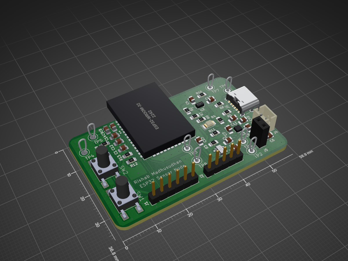
SensorNodeProject is an open-source printed circuit board by rishabmadhusudhan07, from the rishabmadhusudhan07/sensor-node repository on GitHub, published under the MIT licence. It is a 2-layer board of 58.9 × 36.8 mm with 47 parts on 50 nets, routed with 288 tracks and 105 vias.
It is built around the ESP32-WROOM-32E-N4, BH1750FVI-TR and RT9080-33GJ5, with the TPB4056A20-DFGR among its other parts. Its parts include 15 capacitors, 12 resistors, 5 connectors, 4 ICs and 2 switches. It belongs with the ESP32 boards of this library.


A custom ESP32-based weather sensor node targeting six months of battery life and less than 50 µA system current during deep sleep. The project was motivated by gaps observed while mapping environmental data across the Pacific Northwest during a National Weather Service internship.
Planned firmware will use ESP-IDF and statically allocated FreeRTOS tasks for sensor sampling, local logging, wireless transmission, and deep-sleep control. Later revisions may add transmission integrity checks and adaptive sampling based on changing weather conditions.
Status: In development. The PCB has been assembled and confirmed working. BME280 I2C communication is being tested. Chip ID was verified. Compensated temperature/pressure/humidity values are in progress. Project Status.
A low-cost, low-power sensor node could make denser local observations more practical. This project explores the engineering requirements for that type of device.
The following values are estimates based on component datasheets and haven't been verified on assembled hardware.
| Component | Role | Sleep current |
|---|---|---|
| ESP32-WROOM-32E-N4 | MCU + WiFi | ~10 µA |
| BME280 (through-hole breakout, soldered on) | Temp / humidity / pressure, forced mode | ≥0.1 µA sensor only |
| BH1750FVI-TR (bare IC, reflowed) | Ambient light | 1 µA |
| TPB4056A20-DFGR | LiPo charge management | <2 µA |
| RT9080-33GJ5 | 3.3V LDO regulator, 600 mA max | ~2 µA |
Target: <50 µA average system sleep current.
ESP-IDF over Arduino. ESP-IDF was selected to provide direct control over FreeRTOS task creation, static memory allocation, peripheral configuration, and ESP32 sleep/wake behavior.
LDO instead of a buck-boost regulator. An LDO offers a simpler design and lower quiescent current, though reduced usable battery voltage as the LiPo approaches the regulator’s dropout region. The RT9080-33GJ5 was selected for its ~2 µA quiescent current and 600 mA output rating. Did not use MCP1700 because of its 250 mA rating, which isn't enough for WiFi transmission.
No onboard current-sense IC. It needs to measure sleep current in the microamps as well as much larger Wi-Fi transmission currents. Instead of a dedicated IC, test points are placed across a removable jumper. The jumper can be replaced by a larger resistor for controlled sleep measurements or a lower one for active measurements. An INA219 did not provide sufficient dynamic range for both measurements with a single resistor, while the INA228 drew too much current.
Adaptive sampling instead of a fixed interval. The planned firmware will have a rolling window of pressure measurements, estimate the rate of change, and adjust the next sampling interval. Faster changes, such as a cold front or wind shift, will mean more frequent sampling; stable conditions mean longer sleep intervals.
Fully static FreeRTOS allocation. Every task and queue will be created statically to keep predictable memory usage.
├── firmware/       # ESP-IDF project
├── hardware/       # KiCad schematic + PCB layout
└── README.md| Phase | Status |
|---|---|
| Rev A schematic and PCB layout | Complete |
| PCB fabrication and bring-up | Complete |
| Sensor firmware | In progress |
| FreeRTOS task implementation | In Progress |
| Data integrity and Wi-Fi retry pipeline | Not started |
| Power characterization | Not started |
| Field testing | Not started |
MIT — see LICENSE.
| Qty | Value | Footprint | References |
|---|---|---|---|
| 8 | TestPoint | TestPoint:TestPoint_Loop_D2.50mm_Drill1.0mm | TP1, TP2, TP3, TP4, TP5, TP6, TP7, TP8 |
| 7 | 0.1uF | Capacitor_SMD:C_0805_2012Metric_Pad1.18x1.45mm_HandSolder | C1, C4, C7, C9, C11, C12, C13 |
| 4 | 1uF | Capacitor_SMD:C_0805_2012Metric_Pad1.18x1.45mm_HandSolder | C3, C10, C14, C15 |
| 3 | 10uF | Capacitor_SMD:C_0805_2012Metric_Pad1.18x1.45mm_HandSolder | C2, C5, C6 |
| 2 | 10k | Resistor_SMD:R_0805_2012Metric_Pad1.20x1.40mm_HandSolder | R8, R9 |
| 2 | 1M | Resistor_SMD:R_0805_2012Metric_Pad1.20x1.40mm_HandSolder | R12, R13 |
| 2 | 4.7k | Resistor_SMD:R_0805_2012Metric_Pad1.20x1.40mm_HandSolder | R2, R7 |
| 2 | 5.1k | Resistor_SMD:R_0805_2012Metric_Pad1.20x1.40mm_HandSolder | R5, R6 |
| 2 | SW_Push | push button:SW_TS04-66-50-BK-160-SMT | SW1, SW2 |
| 1 | 1.5k | Resistor_SMD:R_0805_2012Metric_Pad1.20x1.40mm_HandSolder | R11 |
| 1 | 1k | Resistor_SMD:R_0805_2012Metric_Pad1.20x1.40mm_HandSolder | R10 |
| 1 | 22uF | Capacitor_SMD:C_0805_2012Metric_Pad1.18x1.45mm_HandSolder | C8 |
| 1 | 500k | Resistor_SMD:R_0805_2012Metric_Pad1.20x1.40mm_HandSolder | R4 |
| 1 | 6k | Resistor_SMD:R_0805_2012Metric_Pad1.20x1.40mm_HandSolder | R3 |
| 1 | BH1750FVI-TR | BH1750FVI-TR:BH1750FVI-TR_ROM | U2 |
| 1 | Conn_01x02_Pin | Connector_JST:JST_PH_B2B-PH-K_1x02_P2.00mm_Vertical | J4 |
| 1 | Conn_01x02_Socket | Connector_PinSocket_2.54mm:PinSocket_1x02_P2.54mm_Vertical | J5 |
| 1 | Conn_01x05_Pin | Connector_PinHeader_2.54mm:PinHeader_1x05_P2.54mm_Vertical | J2 |
| 1 | Conn_01x06_Socket | Connector_PinHeader_2.54mm:PinHeader_1x06_P2.54mm_Vertical | J1 |
| 1 | ESP32-WROOM-32E-N4 | ESP32-WROOM-32E-N4:ESP32WROOM32E_EXP | U1 |
| 1 | LED | LED_SMD:LED_1206_3216Metric_Pad1.42x1.75mm_HandSolder | D1 |
| 1 | RT9080-33GJ5 | RT9080-33GJ5:TSOT-23-5_RIT | U5 |
| 1 | TPB4056A20-DFGR | TPB4056A20-DFGR:DFN2X2-8_TPK | U3 |
| 1 | USB_C_Receptacle_PowerOnly_6P | Connector_USB:USB_C_Receptacle_GCT_USB4125-xx-x_6P_TopMnt_Horizontal | J6 |
It measures 58.9 × 36.8 mm and has 2 copper layers, 1.6 mm thick.
47 parts, built around the ESP32-WROOM-32E-N4, BH1750FVI-TR, RT9080-33GJ5 and TPB4056A20-DFGR. The full list of its parts is on this page, with links to each part's symbol and footprint where PCBKit's library has them.
From the rishabmadhusudhan07/sensor-node repository on GitHub, at the commit this page was made from: the board is hardware/SensorNodeProject.kicad_pcb and its schematic hardware/SensorNodeProject.kicad_sch. PCBKit opens the board in the browser, with nothing to install.
Its repository publishes it under the MIT licence: you may reuse it on that licence's terms (keep the author's notice, and for a copyleft licence share your changes alike).
MoreThanRobotsFR/MTR_C3_TempHum
A tiny temperature, humidity, gas, pressure, ambient light and presence detector (mmWave presence sensor) measurement unit for HomeAssistant using ESPHome


HolTyc/STM32_watch_NFC
Watch using STM32 with LED 7-segment display and RGB display


TobleMiner/catear-pcb
This repo contains the PCB for the Nekomimi project of @BenBE . It will be used to illuminate 3D printed catears.