2 layers
 middelink/MatrixClock2
MatrixClock - source code, schematics and pcb layout
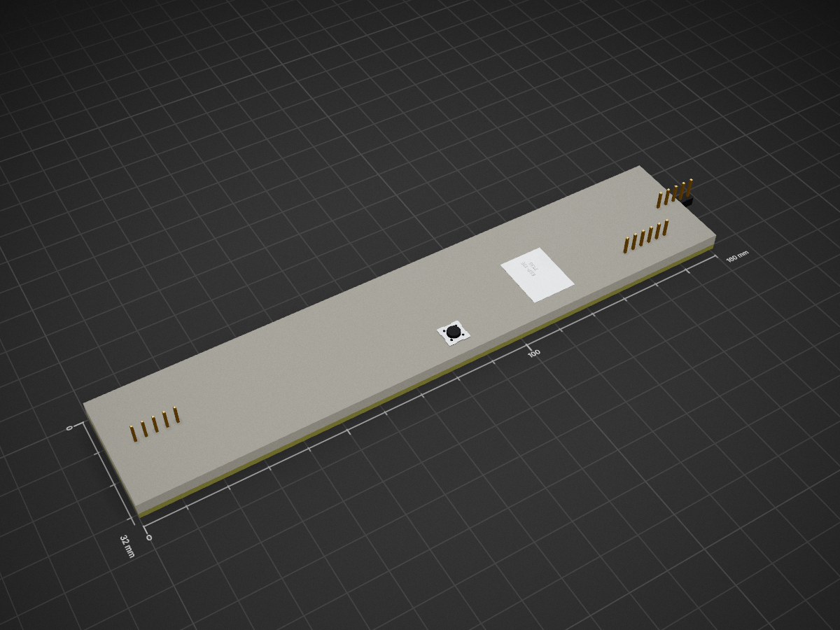
MatrixClock is an open-source printed circuit board by middelink, from the middelink/MatrixClock repository on GitHub, published under the MIT licence. It is a 2-layer board of 160 × 32 mm with 70 parts on 26 nets, routed with 415 tracks and 13 vias.
It is built around the ESP-12E, BH1750FVI-TR and BME280, with the BME680, APDS-9301-020 and LD1117S33TR(MS) among its other parts. Its parts include 11 resistors, 10 capacitors, 6 ICs, 5 connectors and 1 diode. It belongs with the ESP8266 boards of this library.


MatrixClock is both a hardware and software project to create an extensible 40x8 dot matrix display with some sensors attached because, uhm. I could?
Here you will find the both the schematics, pcb layout and source code of my MatrixClock project.
The source is written on a Linux box and compiled/uploaded via the excellent PlatformIO toolkit. The schematics and pcb layout is created in KiCad.
I will not bother to tell you how to compile/upload the code, modify the schema, change the layout, create gerbers and wait patiently for the PCBs to arrive before starting your SMD soldering adventure. Simply because you should not do this if you not exhaustively researched all of the just mentioned area's.
Good luck! Pauline
| Qty | Value | Footprint | References |
|---|---|---|---|
| 30 | VIA-6mm | Private:VIA-6mm | VIA01, VIA02, VIA03, VIA04, VIA05, VIA06, VIA07, VIA07, VIA08, VIA09, VIA10, VIA11, VIA12, VIA13, VIA14, VIA15 +14 |
| 8 | 100nF | Capacitors_SMD:C_0805 | C1, C2, C3, C4, C5, C8, C9, C10 |
| 7 | 10K | Resistors_SMD:R_0805_HandSoldering | R3, R4, R5, R6, R7, R8, R9 |
| 5 | Module_MAX7219 | Private:Module_MAX7219 | M1, M2, M3, M4, M5 |
| 2 | 100K | Resistors_SMD:R_0805_HandSoldering | R1, R2 |
| 2 | CONN_01X05 | Pin_Headers:Pin_Header_Straight_1x05_Pitch2.54mm | J3, J4 |
| 1 | 100uF | Capacitors_SMD:CP_Elec_6.3x5.7 | C7 |
| 1 | 10uF | Capacitors_SMD:CP_Elec_3x5.3 | C6 |
| 1 | 1K | Resistors_SMD:R_0805_HandSoldering | R11 |
| 1 | 1N4148 | Diodes_SMD:D_SOD-123 | D1 |
| 1 | 4K7 | Resistors_SMD:R_0805_HandSoldering | R10 |
| 1 | APDS-9301 | Private:APDS9301 | U4 |
| 1 | BH1750FVI-TR | Private:WSOF6 | U3 |
| 1 | BME280 | Private:BME280 | U5 |
| 1 | BME680 | Private:BME680 | U6 |
| 1 | CONN_01X06 | Pin_Headers:Pin_Header_Straight_1x06_Pitch2.54mm | J2 |
| 1 | DISP_PWR | Private:SOLDER-JUMPER_2-WAY | J5 |
| 1 | ESP-12E | ESP8266:ESP-12E_SMD | U2 |
| 1 | LD1117S33TR | TO_SOT_Packages_SMD:SOT-223-3Lead_TabPin2 | U1 |
| 1 | PNP | TO_SOT_Packages_SMD:SOT-23 | Q1 |
| 1 | SW_Push | Buttons_Switches_SMD:SW_SPST_PTS645 | SW1 |
| 1 | USB_OTG | Private:USB_Micro-B_Vertical_Molex-105133-0001 | J1 |
It measures 160 × 32 mm and has 2 copper layers, 1.6 mm thick.
70 parts, built around the ESP-12E, BH1750FVI-TR, BME280 and BME680. The full list of its parts is on this page, with links to each part's symbol and footprint where PCBKit's library has them.
From the middelink/MatrixClock repository on GitHub, at the commit this page was made from: the board is KiCad/MatrixClock.kicad_pcb. PCBKit opens the board in the browser, with nothing to install.
Its repository publishes it under the MIT licence: you may reuse it on that licence's terms (keep the author's notice, and for a copyleft licence share your changes alike).


TobleMiner/catear-pcb
This repo contains the PCB for the Nekomimi project of @BenBE . It will be used to illuminate 3D printed catears.

MoreThanRobotsFR/MTR_C3_TempHum
A tiny temperature, humidity, gas, pressure, ambient light and presence detector (mmWave presence sensor) measurement unit for HomeAssistant using ESPHome


aluisioalves123/esp32-env-sensor
Placa de sensor ambiental com ESP32-WROOM-32E projetada do zero no KiCad 9: USB-C com CH340C e auto-program, BME280 e BH1750FVI em I2C, regulacao AMS1117-3.3.


huulanka/wisp
Open-source ESP32 room climate monitor — CO2, VOC, humidity, temperature and light sensing with custom PCB, MQTT/HomeKit integration, and OTA firmware updates. Full hardware + software, from schematic to BOM.