

2 layers26.5 × 34.4 mm
PicoLoaderNSB
makeo/PicoLoader
A cheap and easy to install modchip for the Nintendo GameCube!
45 parts320GPL-2.0

Wireless keyboard for the M8 iOS app using Pico 2 W
M8KB is an open-source printed circuit board by rheslip, from the rheslip/M8-BLE-Keyboard-for-the-iOS-App repository on GitHub. It is a 2-layer board of 93 × 80 mm with 26 parts on 40 nets, routed with 130 tracks and 2 vias.
It is built around the 1N5819WS. Its parts include 8 switches, 3 resistors, 2 diodes and 1 capacitor. It belongs with the keyboards and input boards and the RP2040 boards of this library.
BLE Wireless Keyboard for the M8 iOS App
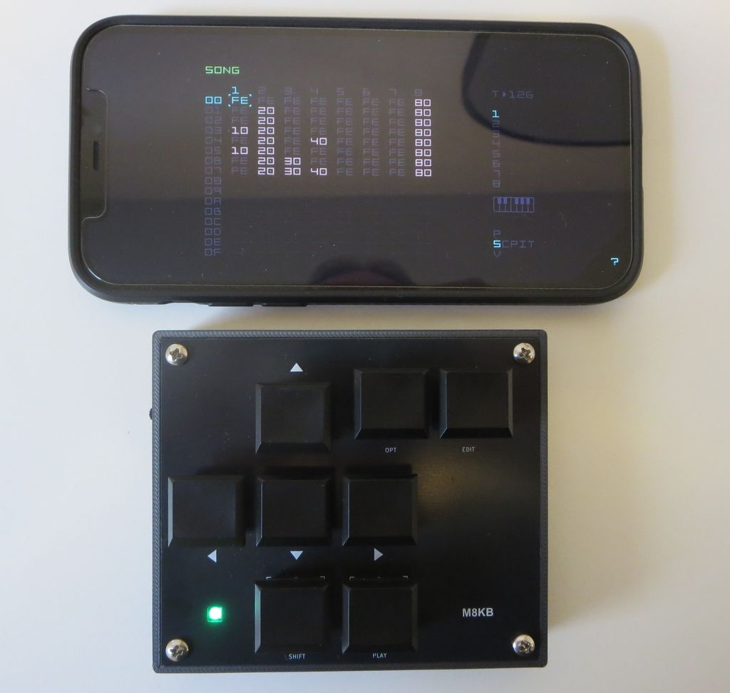
When I saw that Dirtywave had released an M8 app on iOS one my first thoughts was to make an M8 like keyboard for it. I have an M8 headless that is almost identical to the real M8 and I wanted to leverage the muscle memory I had developed for that.
Altho it was created for use with the iOS app, with some software modifications it would work on a PC with the M8 Headless as well.
Oct 3/2026 - more or less final version of the code which shows battery levels on the RGB LED
Sept 17/2026 - added hardware design files for PCB and two enclosure variants (AAA battery and LiPo with charging jack) - tested and working OK
Video demo of the final version https://www.youtube.com/watch?v=-Xh-XhrWJC8&t=2s
The prototype worked very well so I have designed a PCB and enclosure which more or less duplicates the M8 V1 design - eight Kailh switches, approx 97mm x 84mm x18mm, white silkscreen. It has a small RGB led for indicating battery status, pads for a switch and pads for a lipo charger module as well.
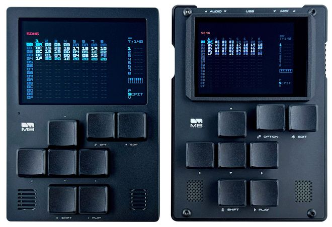
M8 V1 and V2 images for reference
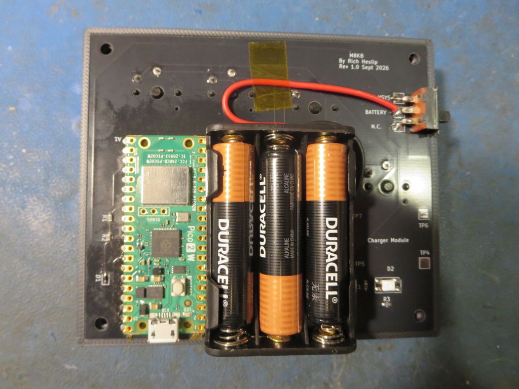
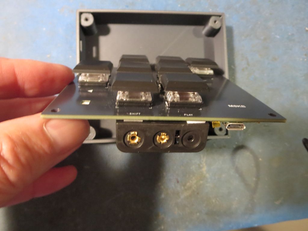
PCB images:
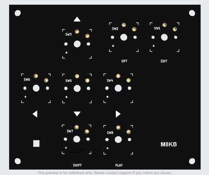
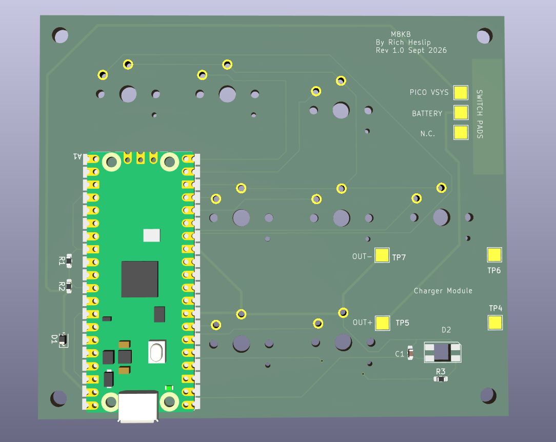
You may notice there is no ground fill on the board. This is intentional - a large GND plane near the antenna will mess with the BLE signal. I also wanted a clean front panel with no visible planes/traces/vias.
3D Renders of the enclosure. Note the cutouts for USB-C charging jack and switch on the LiPo version. A version with no USB jack is provided for use with a AAA battery holder.
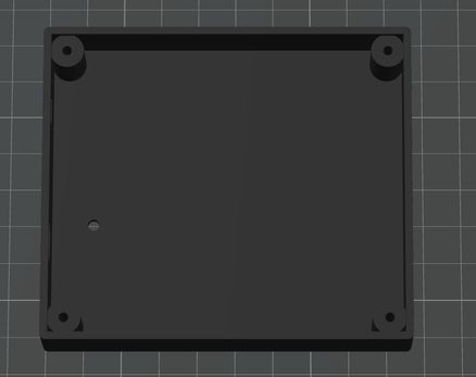
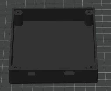
Batteries
I use LiPo batteries and small charger modules from AliExpress. The PCB footprint is for this one which has a LiPo protection circuit as well but you can barnacle almost any of these on and make it work.
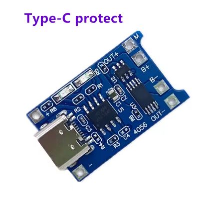
CAUTION this TP4056 charger module is set up for 1A charge rate which is too high for most small LiPo's To be safe you will want to change the current setting resistor to something like 1/3 of the battery capacity.
LiPo batteries are a fire hazard!!! Do not use a LiPo unless you are comfortable modifying the module appropriately, testing it, and are willing to take the risk
Alternatively use 3 AAA batteries which is much safer. You can use 2x AAA as well but the battery life will be reduced by 1/3. The battery indicator is set up for the range of a LiPo 4.2V full, 3V cutoff which is about the same voltage range as three AAA. If you use something else you will need to modify the sketch.
Power consumption of the Pico 2 W running this sketch is around 40ma at 5V (0.2 watts). If you use three AAA alkalines (around 3WH) the batteries should last around 15 hours. An 800 Mah LiPo should have about the same battery life. Unfortunately the Pico 2 BLE stack does not support power management or underclocking which would have been nice to extend the battery life.
Usage
I have not had much luck getting the iOS bluetooth settings to see the M8KB device directly. Adafruit's Bluefruit Connect app sees it and pairs with it no problem. After pairing with Bluefruit Connect, iOS will automatically connect to it every time. This is not the first time I've have trouble with bluetooth devices on iOS. There seem to be some subtle incompatibilies between the Pico's implementation of BLE and what Apple wants to see.
If you recompile and reinstall the firmware you have to forget the device and pair it again on your iPad/iPhone.
The default key bindings are set up to work with the M8 app default keyboard assignment but you may have to re-bind the key assignments in the M8 app to get everything working correctly. In particular the M8 app sees the SHIFT and EDIT keys as the same key until you re-bind them. I think this is because the Arduino keyboard library treats the shift key as a modifier and not as a separate key. You will only have to do this once - the M8 app remembers the key bindings.
Another oddity is that if you are using the M8 app in AUM when you switch to another AUV3 plugin and come back to M8 it loses the connection to M8KB. You can restore it by double tapping the screen to hide/show the on screen controls. M8KB does not show up in the device list in AUM either but it works OK other than the aforementioned disconnect. More weirdness with Pico + iOS BLE or perhaps a bug in the M8 app.
It connects to a PC but doesn't work with M8 web display. It would probably work by changing the Pico library from keyboardBLE to gamepadBLE. More testing is needed.
Assembly
Solder the three 0603 resistors, the .1u cap and the schottky diode. Solder in the RGB LED making sure that the orientation matches the silkscreen and make sure the lens is facing the FRONT of the PCB. If you don't want to source this LED, you can barnacle an SMT LED or even a 3mm LED to the pads but you will have to modify the sketch to make it blink or something when the battery is low.
Solder the Pico 2W to the pads. If you think you may want to remove it at some point best to use small wires or perhaps put some kapton tape on the bottom of the Pico - if the pads have been soldered directly to the PCB pads its very hard to desolder. Also make sure the USB connector edge is flush with the PCB edge - you don't want it to stick out because there is no provision for it in the enclosure. ie load the firmware with the board out of the enclosure.
Solder in the Kailh 1350 switches so the plungers are on the front side of the PCB (obviously). These switches are the same ones used on the M8 and they are available with different actuation forces and "clickiness". The M8 has removable switches - I had the sockets in the design and then took them out. M8 users probably already know which switches they like.
If you are using a LiPo, solder the charger module to the four pads so the USB jack faces to the left with the board switch side up. Solder the negative battery lead to the B- pad on the charger module. At this point its a very good idea to put a current meter between the B+ pad and the battery + lead - make sure the power switch is off. If everything is OK there should be just a very tiny leakage current. If not, you probably have a bad module. I always check the charging current at this stage as well.
If you are using a AAA holder, solder the +ve lead to the OUT+ pad and the -ve lead to OUT- pad. A 3x AAA battery holder should just fit between the Pico and the charger pads and can be stuck to the PCB with double sided foam tape.
I couldn't find a suitable PCB mounted R/A slide switch so I went with PCB pads so you can solder in whatever you have. I use small slide switches about 5mm thick by 13mm wide. Glue it to the PCB and wire the switch leads to the provided pads. Make sure the switch is flush with the edge of the PCB and aligned with the switch cutout in the enclosure.
The mounting holes in the enclosure are sized for 4-40 or 3mm screws - tap the holes. You could also use small wood or plastic cutting screws.
| Qty | Value | Footprint | References |
|---|---|---|---|
| 8 | SW_Push | Kaihl 1350:SW_PG1350 | SW1, SW2, SW3, SW4, SW5, SW6, SW7, SW8 |
| 4 | MountingHole | MountingHole:MountingHole_3.2mm_M3_ISO14580 | H1, H2, H3, H4 |
| 2 | 100k | Resistor_SMD:R_0603_1608Metric_Pad0.98x0.95mm_HandSolder | R1, R2 |
| 2 | SW | TestPoint:TestPoint_Pad_2.5x2.5mm | TP2, TP3 |
| 2 | ~ | TestPoint:TestPoint_Pad_2.5x2.5mm | TP4, TP6 |
| 1 | 0.1u | Capacitor_SMD:C_0603_1608Metric_Pad1.08x0.95mm_HandSolder | C1 |
| 1 | 1N5819WS | Diode_SMD:D_SOD-323 | D1 |
| 1 | 33R | Resistor_SMD:R_0603_1608Metric_Pad0.98x0.95mm_HandSolder | R3 |
| 1 | OUT+ | TestPoint:TestPoint_Pad_2.5x2.5mm | TP5 |
| 1 | OUT- | TestPoint:TestPoint_Pad_2.5x2.5mm | TP7 |
| 1 | PWR_IN | TestPoint:TestPoint_Pad_2.5x2.5mm | TP1 |
| 1 | RaspberryPi_Pico_W | MyLibrary:RaspberryPi_Pico_SMD | A1 |
| 1 | SK6812E-MINI | MyLibrary:LED_OPSCO_SK6812_MINI-E_5.0x5.0mm_P3.1mm_rearmount | D2 |
makeo/PicoLoader
A cheap and easy to install modchip for the Nintendo GameCube!


AzonInc/Doorman
ESP32-S3 based Intercom Gateway (TCS / Koch / Niko / Scantron / Analogue Systems)

sd2psx/pcb
The PCB must be produced in 0.8mm thickness. Production files are provided under the "Releases" tab. These do not include the through-hole OLED module.

plinkysynth/plinky_public
a public release of the plinky sw and hw


o7-machinehum/Blackpants
Open blackpants.kicadpro for the active A523 schematic and PCB. It replaces the A33 hierarchy and uses AXP717C + AXP323 with 2GB LPDDR4.

zoemaestra/hair-electrolysis-machine-usb-c
A fork of scd31's hair electrolysis machine but with USB-C and optimised for cheaper assembly with JLCPCB
It measures 93 × 80 mm and has 2 copper layers, 1.6 mm thick.
26 parts, built around the 1N5819WS. The full list of its parts is on this page, with links to each part's symbol and footprint where PCBKit's library has them.
From the rheslip/M8-BLE-Keyboard-for-the-iOS-App repository on GitHub, at the commit this page was made from: the board is KiCad/M8KB/M8KB.kicad_pcb and its schematic KiCad/M8KB/M8KB.kicad_sch. PCBKit opens the board in the browser, with nothing to install.
Its repository states no licence, so its author keeps all rights: ask rheslip before reusing the design.