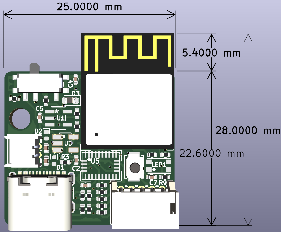
2 layers25 × 22.6 mm

 ReSummit/uSlime4
Micro form of SlimeVR trackers using BNO085
USlime BNO085 Module is an open-source printed circuit board by ReSummit, from the ReSummit/uSlime repository on GitHub, published under the GPL-3.0 licence. It is a 2-layer board of 16.7 × 12.8 mm with 19 parts on 21 nets, routed with 122 tracks and 10 vias.
It is built around the BNO085 and X1502WR-05K-N0SN. Its parts include 7 resistors, 4 capacitors, 2 connectors and 1 IC.



Micro form of SlimeVR trackers using BNO085 and ESP32-C6-MINI module, as small as possible
Limited to 1 sided PCB but utilizes two layer to achieve a maximal dimension of 25mm x 28mm (including the ESP32-C6-MINI module)
Also includes some test points if you wanna add idk RGB lights to it or something like that lol
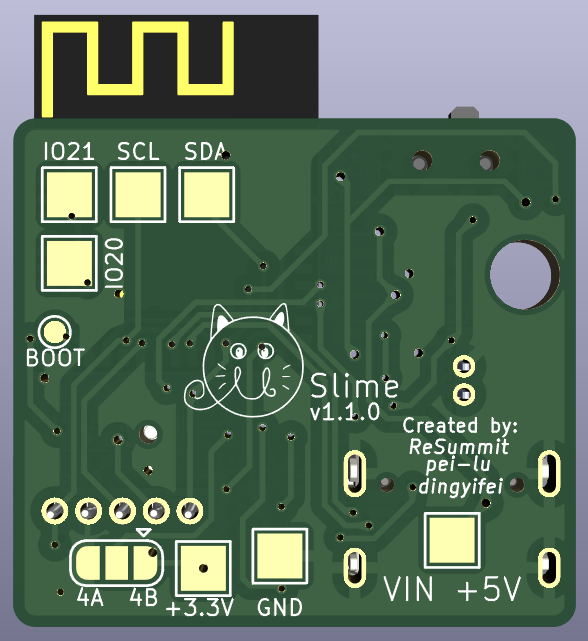
Currently, v1.0.0 is the preferred PCB version and is listed in the releases. As a note, your red charge LED will always be on while the device is on. While this makes for a good indicator that your tracker is on, some may not like that the LED is always on. v1.1.0 fixes this but results in a long trace, change in pinout, and additional components needed.
If you do not mind the always on LED, use v1.0.0 as it is less likely to result in RF issues. If you are bothered by the LED, use a 2k or higher SMD resistor value or use v1.1.0.
On variants, there are currently three different types of main board PCBs and 2 types of supplementary modules. The first kind are listed as follows:
For supplementary modules, the variants are as follows:
Bill of materials (BOMs) can be found in the bom folder within the respective PCB folder. These are generated on a by release basis, so they may not be up to date. It is highly recommended to generate the BOM using the "Interactive Html Bom" plugin found in typical KiCAD repository plugins.
Following the BOM placements using a BOM plugin to show where components are placed is mandatory, as there is no space for reference designators on the PCB.
In addition to this, a hot plate, solder paste, and some needle tipped tweezers are also required. Flux may also be needed to fix any bridges that pop up on the board. Obviously, the components on the BOM are also required.
When ordering the PCB, choose to place the JLC PCB indicator as a preferred spot is placed on the PCB itself (if using JLCPCB for PCB production). You should also get a stencil to put solder paste on the PCB.
Again, following the BOM placements using a BOM plugin to show where components are placed is mandatory, as there is no space for reference designators on the PCB. Place solder paste on the PCB. Afterwards, follow the Interactive HTML BOM to place all the capacitors, resistors, IMU, and MCU on the PCB. When ready, you can then place this on a hot plate. Please make sure that there are no bridges on the BNO085 or the USB C connector, as these can cause issues with functionality.
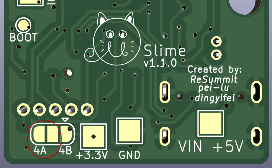
Before testing and using, make sure to bridge the address bridge pads on the back of the PCB. Verify that the board and the IMU functions by flashing the ESP32-C6 firmware first. If there is no address response, something may be wrong with the IMU (more likely to fail). Once you have verified that the IMU and MCU works, you can then solder the rest of the THT components such as the external IMU connector and battery connector.
The PCB currently uses a ESP32-C6 or equivalent MCU. Right now, there is a pull request to introduce this MCU into the SlimeVR ESP32 firmware located here:
SlimeVR ESP32-C6 Pull Request
The Arduino core is technically updated but is still pending its full support to the ESP32-C6 line. Therefore, treat this as a beta firmware and subject to broken features or bugs.
Due to the inherent nature of this PCB, there is a chance that this PCB may produce RF. We have not tested for RF emission but regardless, be careful if using this in RF restricted environments.
Also, the main PCB does not have USB voltage protection circuits! Unfortunately, we ran out of time for the release but it is plausible to add it...
In addition, due to the single-sided PCB layout, this is not technically as small as it could be. There have been countless videos that showcase the design possibly being smaller. Some resistor and SMD components can also be moved to the back due to the ease in soldering those components. However, those are slated for a v2.0.0 PCB and is not expected to be released within anytime this year.
Lastly, it is known that the charger SMD compoenent tends to heat up rather quickly while charging the battery. This shouldn't reach the melting point of solder but it is worth mentioning; perhaps a more efficient IC would be better here.
Some footprints and symbols were used from other sources:
| Qty | Value | Footprint | References |
|---|---|---|---|
| 4 | 0.1uF | Capacitor_SMD:C_0402_1005Metric | C1, C2, C3, C4 |
| 4 | 2.2k | Resistor_SMD:R_0402_1005Metric | R3, R4, R6, R7 |
| 3 | 10k | Resistor_SMD:R_0402_1005Metric | R1, R2, R5 |
| 2 | LOGO | uSlime-libs:uSlime_logo | G***, G*** |
| 1 | BNO085 | uSlime-libs:BNO080 | U1 |
| 1 | Conn_01x05 | Connector_PinHeader_2.54mm:PinHeader_1x05_P2.54mm_Vertical | J1 |
| 1 | Jumper_3_Open | Jumper:SolderJumper-3_P1.3mm_Open_RoundedPad1.0x1.5mm | JP1 |
| 1 | X1502WR-05K-N0SN | uSlime-libs:CONN-TH_5P-P1.50_X1502WR-05K-N0SN | CN1 |
The 17 most common of 19 parts.


AFS-pt/PROMETHEUS-1
Documentation lives here: https://afs-pt.github.io/PROMETHEUS-1


rishivg/IO-SDR
Open-Source software-defined FPGA radio hardware platform


codinga593/IRIS
A next generation model rocket focused on a precise propulsive landing on a tower.

SunnyYoshimitsu/Reconfigurable-Space-Compute-Cluster
Here will be the repository for an "extremely reconfigurable satellite" aimed toward at competing in NASA Minds and hopefully assist Artemis in its missions.
It measures 16.7 × 12.8 mm and has 2 copper layers, 1.6 mm thick.
19 parts, built around the BNO085 and X1502WR-05K-N0SN. The full list of its parts is on this page, with links to each part's symbol and footprint where PCBKit's library has them.
From the ReSummit/uSlime repository on GitHub, at the commit this page was made from: the board is uSlime_BNO085_Module/uSlime_BNO085_Module.kicad_pcb and its schematic uSlime_BNO085/BNO085.kicad_sch. PCBKit opens the board in the browser, with nothing to install.
Its repository publishes it under the GPL-3.0 licence: you may reuse it on that licence's terms (keep the author's notice, and for a copyleft licence share your changes alike).