
4 layers48 × 35 mm

 renesas/da14695-module-pico1
The Renesas DA14695MOD Pico board is a versatile 2-layer development board designed with compatibility and functionality in mind.
690 module pico is an open-source printed circuit board by renesas, from the renesas/da14695-module-pico repository on GitHub. It is a 2-layer board of 67.7 × 21 mm with 23 parts on 52 nets, routed with 607 tracks and 124 vias.
It is built around the USBLC6-2P6. Its parts include 3 resistors, 2 ICs, 2 connectors, 2 switches and 1 diode. It belongs with the RP2040 boards of this library.
The Renesas DA14695MOD Pico board is a versatile 2-layer development board designed with compatibility and functionality in mind. Designed to be compatible with the Pico pinout, this board offers a range of features including Bluetooth Low Energy (BLE) capabilities, USB connectivity, a battery connector equipped with an on-chip charger, and 4 MB of onboard FLASH storage.
The board is based on the SmartBond DA14695 Bluetooth low energy 5.2 system-on-chip (SoC), making it a comprehensive solution for various applications. The DA14695 Module encompasses all the hardware features and capabilities of the DA14695 SoC, with integrated passives, an antenna, a 32Mbit QSPI FLASH, and user-friendly software support. The module's design focuses on broad market use, offering certifications across regions. This approach translates to reduced development costs, minimized risks, and faster time-to-market.
For detailed technical specifications of the DA14695 Module, refer to the Renesas website.
This GitHub repository houses all the design files for the DA14695MOD Pico board. These files are compatible with KiCAD 6. The full schematic is included as pdf PDF here.
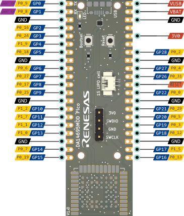
To help you get started quickly, here's a visual representation of the board's pinout:
| Qty | Value | Footprint | References |
|---|---|---|---|
| 2 | 10k | Resistor_SMD:R_0603_1608Metric | R2, R3 |
| 1 | 470 | Resistor_SMD:R_0603_1608Metric | R1 |
| 1 | Battery_Cell | Connector_Molex:Molex_PicoBlade_53261-0271_1x02-1MP_P1.25mm_Horizontal | BT1 |
| 1 | Bootsel | Button_Switch_SMD:SW_SPST_B3U-1000P | SW1 |
| 1 | Conn_01x04_Male | Connector_PinHeader_2.54mm:PinHeader_1x04_P2.54mm_Vertical | J1 |
| 1 | DA14695_000HQ2 | DA14695_000HQ2:MODULE_DA14695_000HQ2 | U2 |
| 1 | GND | TestPoint:TestPoint_Pad_1.0x1.0mm_custom | TP9 |
| 1 | LOGO | LOGO | G*** |
| 1 | Reset | Button_Switch_SMD:SW_SPST_B3U-1000P | SW2 |
| 1 | UART_RX | TestPoint:TestPoint_Pad_1.0x1.0mm_custom | TP6 |
| 1 | UART_TX | TestPoint:TestPoint_Pad_1.0x1.0mm_custom | TP5 |
| 1 | USBLC6-2P6 | Package_TO_SOT_SMD:SOT-666 | U1 |
| 1 | USB_B_Micro | Connector_USB:USB_Micro-B_Amphenol_10118194_Horizontal | J2 |
| 1 | USB_N | TestPoint:TestPoint_Pad_1.0x1.0mm_custom | TP4 |
| 1 | USB_P | TestPoint:TestPoint_Pad_1.0x1.0mm_custom | TP3 |
| 1 | Vbat | TestPoint:TestPoint_Pad_1.0x1.0mm_custom | TP1 |
| 1 | Vbus | TestPoint:TestPoint_Pad_1.0x1.0mm_custom | TP2 |
| 1 | pico | Module:Pico | B1 |
| 1 | usr_led | LED_SMD:LED_0603_1608Metric | D1 |
| 1 | ~{Bootsel} | TestPoint:TestPoint_Pad_1.0x1.0mm_custom | TP7 |
| 1 | ~{RST} | TestPoint:TestPoint_Pad_1.0x1.0mm_custom | TP8 |
The 22 most common of 23 parts.

Bastardkb/Dilemma
The Dilemma is a vertical stagger low-profile keyboard with mods.


Twisted-Fields/rp2040-motor-controller
A dual channel brushless motor controller based on the RP2040 microcontroller, designed in Kicad.


ZSWatch/Watch-DevKit-HW
The hardware repo for the ZSWatch Development Kit.
It measures 67.7 × 21 mm and has 2 copper layers, 1.6 mm thick.
23 parts, built around the USBLC6-2P6. The full list of its parts is on this page, with links to each part's symbol and footprint where PCBKit's library has them.
From the renesas/da14695-module-pico repository on GitHub, at the commit this page was made from: the board is 690 module pico.kicad_pcb and its schematic 690 module pico.kicad_sch. PCBKit opens the board in the browser, with nothing to install.
Its repository states no licence, so its author keeps all rights: ask renesas before reusing the design.