
4 layers66 × 42 mm
Sbc
vd-rd/sbc_at91sam9g20
Open hardware SBC module based on AT91SAM9G20 @400MHz with 128MB RAM
116 parts2

 rede97/picoprobe-promicro
debugprobe by rp2040 promicro
Picoprobe is an open-source printed circuit board by rede97, from the rede97/picoprobe-promicro repository on GitHub. It is a 2-layer board of 24 × 41 mm with 34 parts on 47 nets, routed with 145 tracks and 98 vias.
It is built around the 74AUP1G17GW. Its parts include 18 resistors, 5 diodes, 4 capacitors, 4 connectors and 3 ICs.
A Raspberry Pi Debug Probe expansion board based on the RP2040 Pro Micro core module. The circuit is fully compatible with the official Raspberry Pi Debug Probe — simply plug a RP2040 Pro Micro onto this board, flash the official Debug Probe firmware from Raspberry Pi, and you're ready to go. No custom firmware needed.
The RP2040 Pro Micro has onboard Boot and Reset buttons, making firmware flashing effortless: hold Boot → press Reset → release Boot, and a USB mass storage drive appears — just drag and drop the .uf2 firmware file. No jumper wires or complicated steps required.
What's truly surprising is how well the Raspberry Pi Debug Probe works beyond its intended target. Its compatibility and reliability are far beyond expectations. It not only handles RP2040 chips perfectly, but also delivers rock-solid debugging and flashing for a wide range of ARM microcontrollers and SoCs — the full STM32 lineup, Nordic chips like the nRF52840, and virtually any Cortex-M core MCU.
Thanks to the RP2040's PIO hardware, the Debug Probe achieves exceptionally fast SWD transfer speeds, matching or exceeding some USB high-speed debuggers in practice. Over long debugging sessions across various target chips, it shows none of the common issues — no disconnections, no timeouts, no failed device recognition.
The official Raspberry Pi Debug Probe has a few shortcomings:
Meanwhile, open-source DAPLink solutions generally have worse compatibility and stability across ARM chips compared to the Raspberry Pi Debug Probe.
This is one of the project's biggest strengths:
This project currently supports SWD only, not JTAG. From a practical standpoint:
Future firmware-level JTAG support is not out of the question (the RP2040's PIO is capable in hardware), but there are no concrete plans at this stage.
Rather than designing a complete debugger from scratch, this project pairs a widely available RP2040 Pro Micro module with a dedicated expansion board:
| Front | Back |
|---|---|
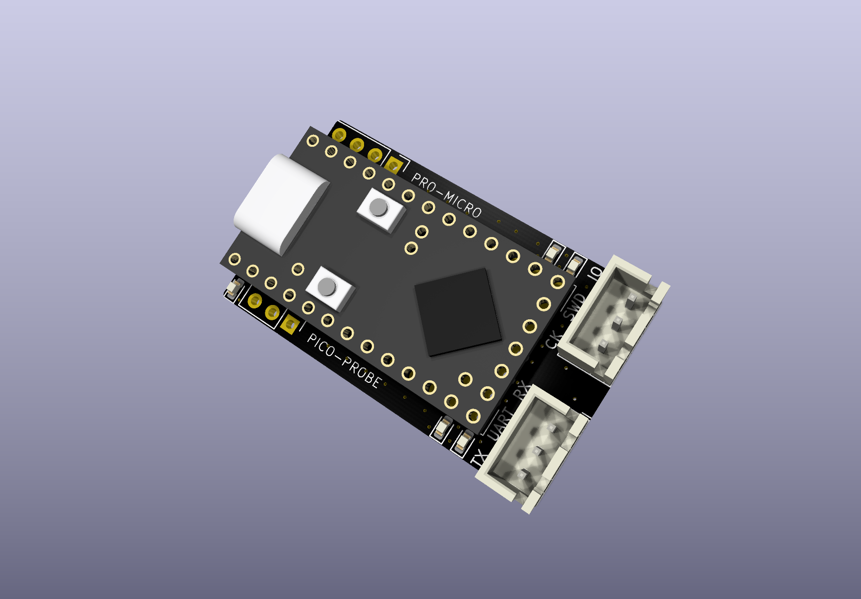 | 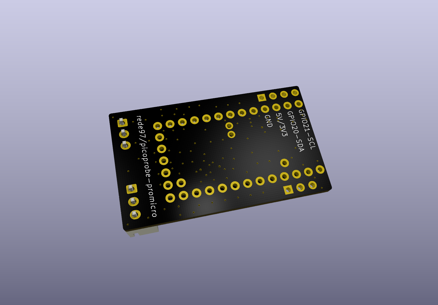 |
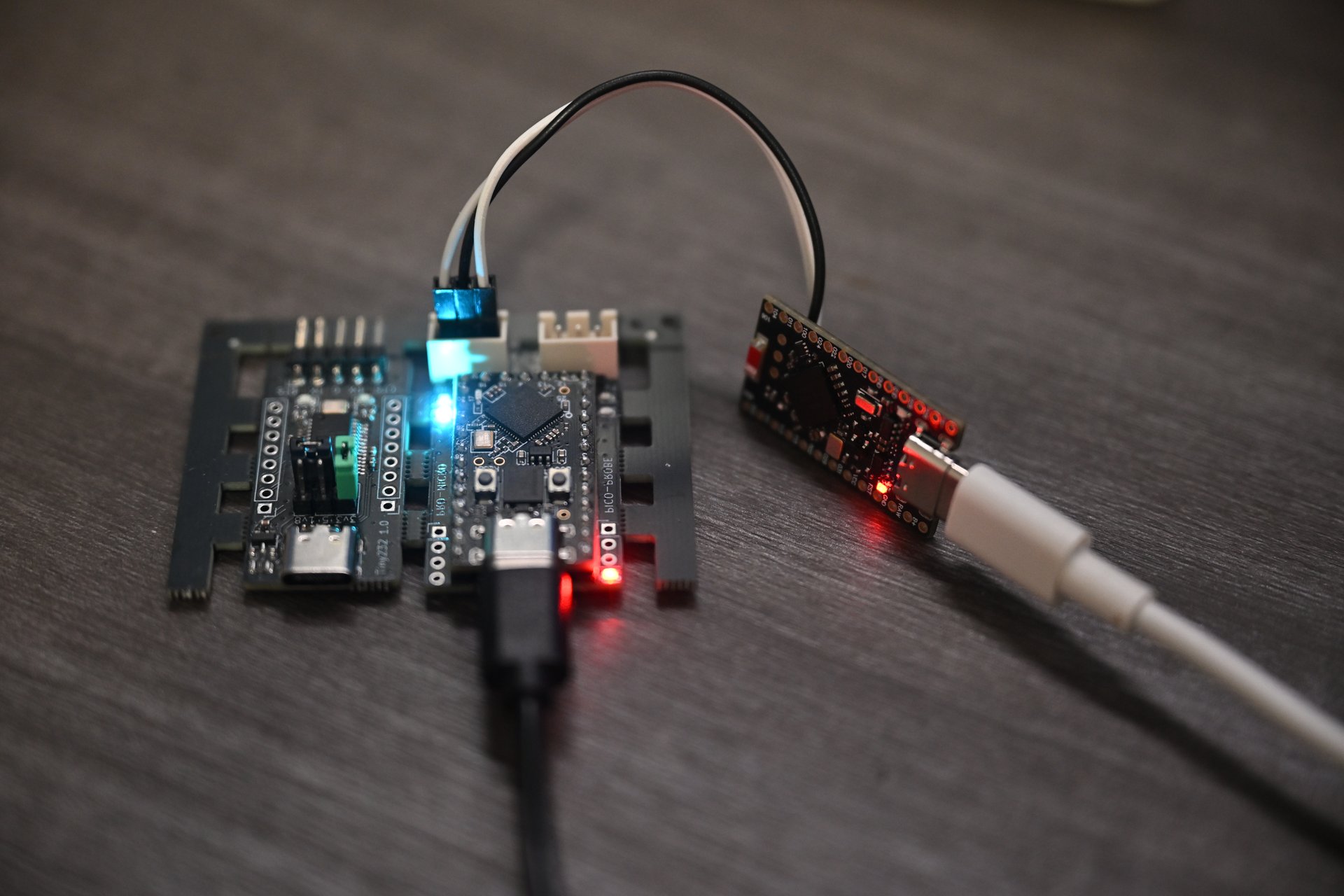
This debugger works perfectly with both the Raspberry Pi Pico 2 and the nRF52840 — rock-solid in practice, with very fast download speeds.
The Pro Micro is mounted on the board via pin headers and female header sockets. Plug it in to debug; pull it off anytime and reuse the module in other projects.
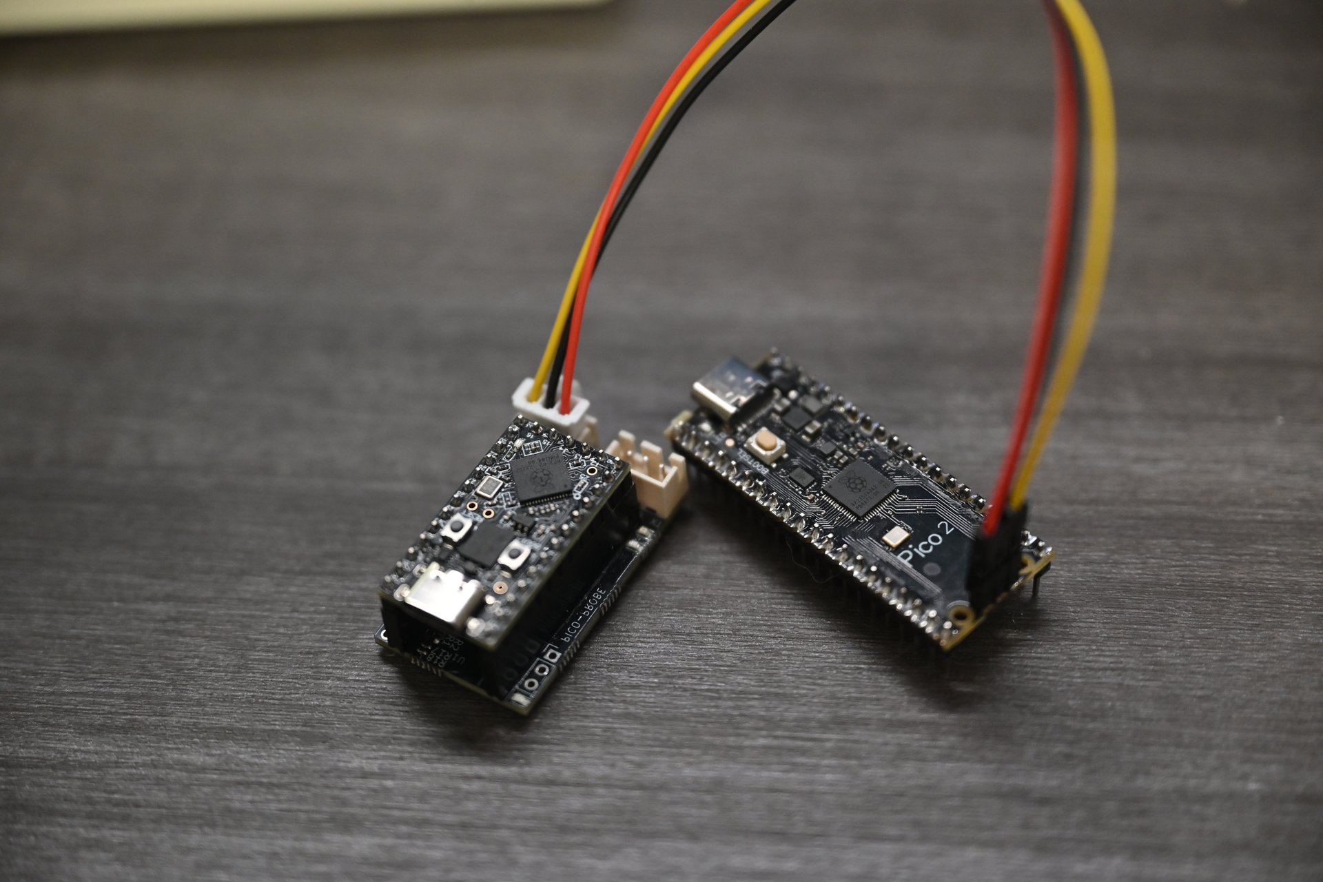
The Pro Micro is soldered directly onto the board as a single, integrated unit. This version is smaller in volume, and is otherwise functionally identical to the detachable version — same circuit, same performance.
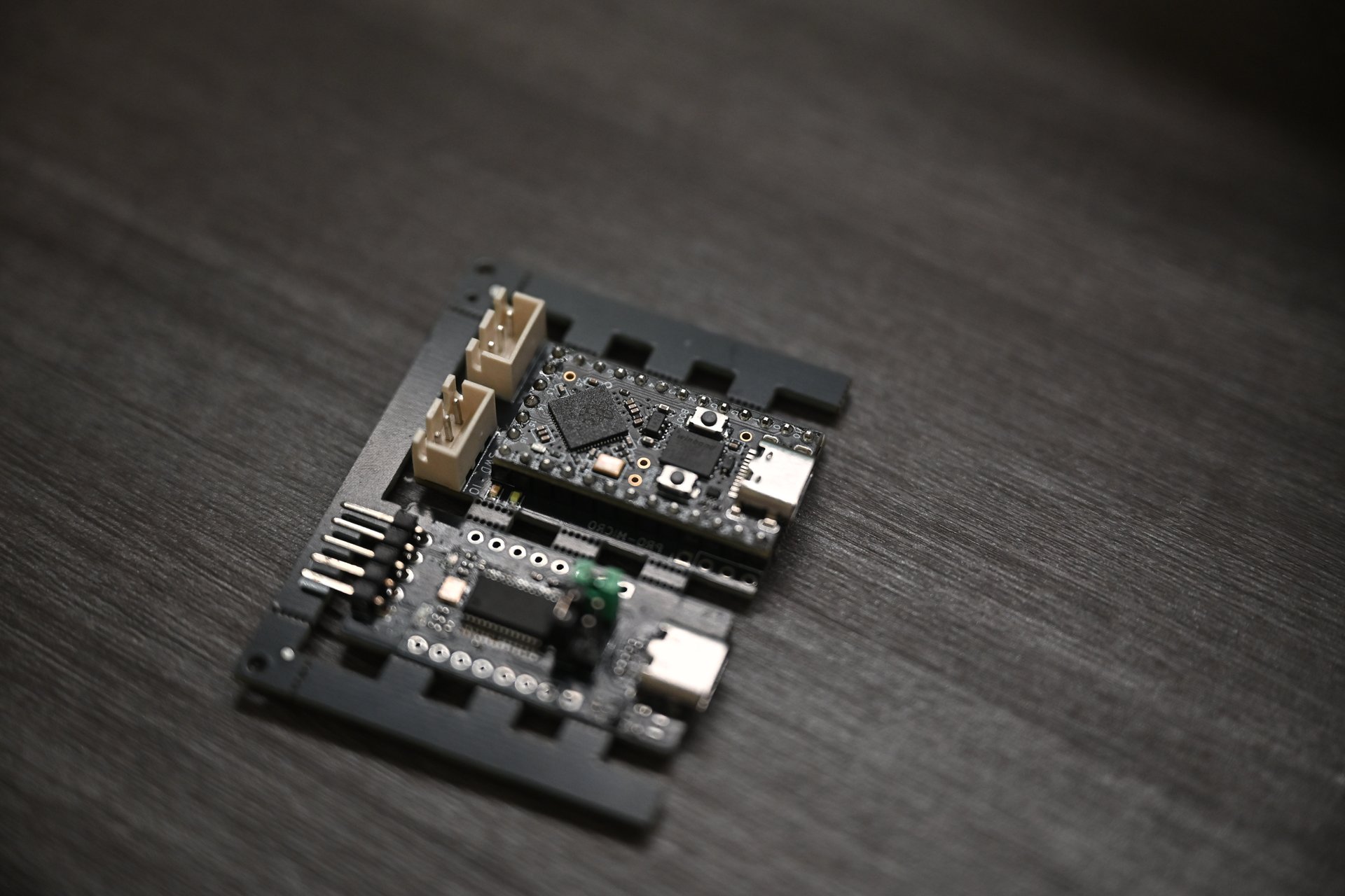
Debugging and flashing an nRF52840 target over SWD. Works flawlessly, with very fast download speeds.
├── hardware/
│   ├── picoprobe.kicad_sch      # Schematic
│   ├── picoprobe.kicad_pcb      # PCB layout
│   ├── picoprobe.kicad_pro      # KiCad project file
│   ├── picoprobe-front.png      # Front render
│   ├── picoprobe-back.png       # Back render
│   ├── picoprobe_sch.pdf        # Schematic PDF
│   ├── picture/                 # Real-world photos
│   └── kicad_pro_micro_rp2040/  # Pro Micro RP2040 footprint library (submodule)
├── README.md
└── README_CN.md| Qty | Value | Footprint | References |
|---|---|---|---|
| 6 | 100R | Resistor_SMD:R_0402_1005Metric | R5, R6, R7, R8, R11, R12 |
| 5 | 470R | Resistor_SMD:R_0402_1005Metric | R3, R13, R14, R15, R16 |
| 3 | 4.7k | Resistor_SMD:R_0402_1005Metric | R17, R18, R19 |
| 2 | 0.1u | Capacitor_SMD:C_0402_1005Metric | C3, C4 |
| 2 | 0R(NC) | Resistor_SMD:R_0402_1005Metric | R9, R10 |
| 2 | 4.7u | Capacitor_SMD:C_0402_1005Metric | C1, C2 |
| 2 | 74AUP1G17 | Package_TO_SOT_SMD:SOT-353_SC-70-5 | U2, U3 |
| 2 | Conn_01x03_Pin | Connector_JST:JST_XH_B3B-XH-A_1x03_P2.50mm_Vertical | J3, J4 |
| 2 | GREEN LED | LED_SMD:LED_0603_1608Metric | D2, D4 |
| 2 | YELLOW LED | LED_SMD:LED_0603_1608Metric | D3, D5 |
| 1 | 0R | Resistor_SMD:R_0603_1608Metric | R2 |
| 1 | 0R(NC) | Resistor_SMD:R_0603_1608Metric | R1 |
| 1 | Conn_01x03_Pin | Connector_PinHeader_2.54mm:PinHeader_1x03_P2.54mm_Vertical | J2 |
| 1 | Conn_01x04_Pin | Connector_PinHeader_2.54mm:PinHeader_1x04_P2.54mm_Vertical | J1 |
| 1 | RED LED | LED_SMD:LED_0603_1608Metric | D1 |
| 1 | ~ | pro_micro_rp2040:pro_micro_rp2040 | U1 |
vd-rd/sbc_at91sam9g20
Open hardware SBC module based on AT91SAM9G20 @400MHz with 128MB RAM


FrameworkComputer/ExpansionCards
Reference designs and documentation to create Expansion Cards for the Framework Laptop

mntmn/amiga2000-gfxcard
MNT VA2000, an Open Source Amiga 2/3/4000 Graphics Card (Zorro II/III), written in Verilog

hackclub/OnBoard
💡 Join 1,000 teenagers and make your first PCB with a $100 grant!

It measures 24 × 41 mm and has 2 copper layers, 1.6 mm thick.
34 parts, built around the 74AUP1G17GW. The full list of its parts is on this page, with links to each part's symbol and footprint where PCBKit's library has them.
From the rede97/picoprobe-promicro repository on GitHub, at the commit this page was made from: the board is hardware/picoprobe.kicad_pcb and its schematic hardware/picoprobe.kicad_sch. PCBKit opens the board in the browser, with nothing to install.
Its repository states no licence, so its author keeps all rights: ask rede97 before reusing the design.