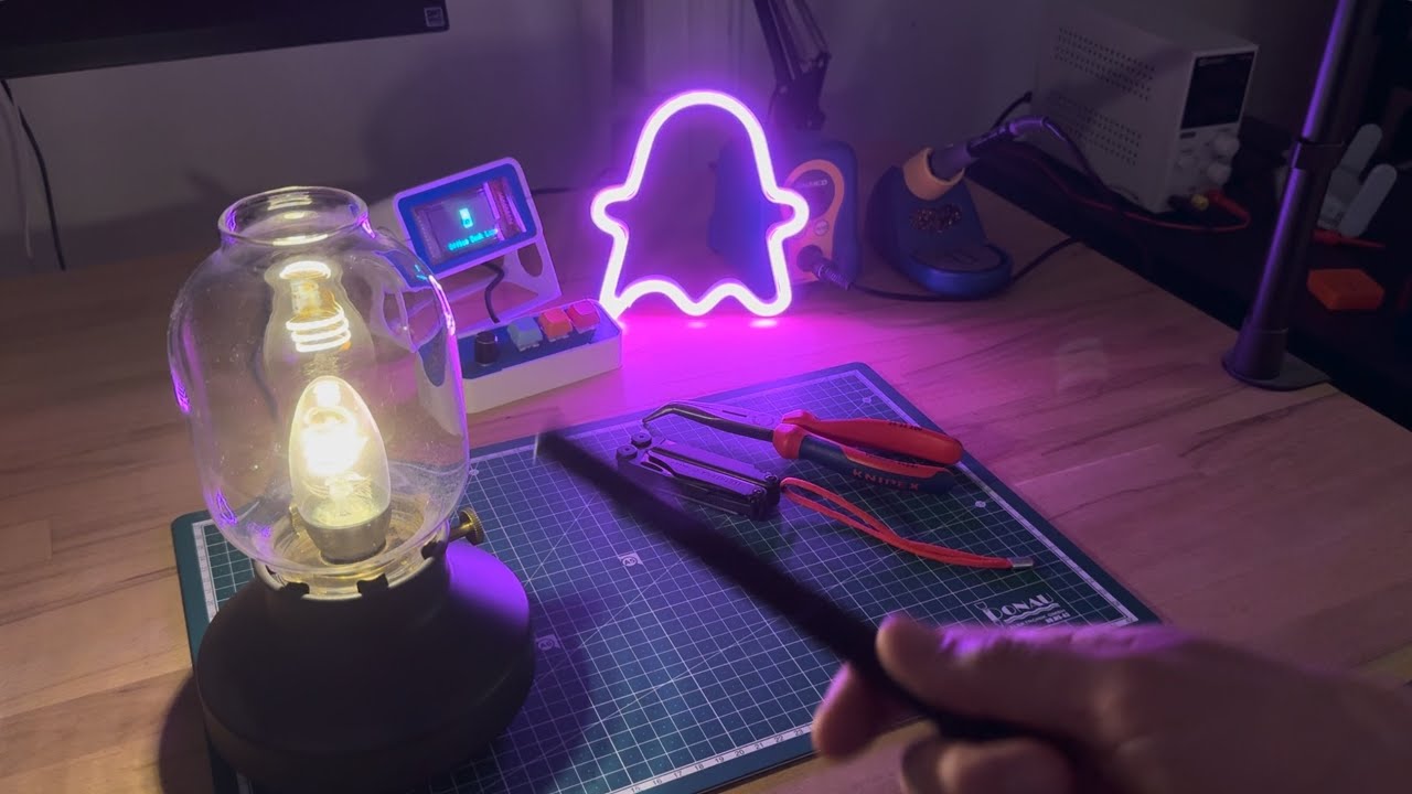
spellcaster is a home automation magic wand. Click on the thumbnail above to watch it in action.
How does it work?
An accelerometer and gyroscope are used to capture gestures ("spells"). Cast spells are then compared against previously stored ones. An action is triggered if there's a good match.
Different actions can be triggered. For example:
- A BTHome.io Bluetooth Low Energy (BLE) packet can be emitted and handled in Home Assistant.
- A Zigbee Cluster action, similarly handled in Home Assistant automations
- A BLE-HID to simulate a key press on a computer, macro pad-style
In the "Software" section below, there are some firmware samples for each of these actions and more.
This blog post has a deeper dive into how everything works.
Project status
It sort of works, but there are caveats. Reliability and usability need improvement -- it's easy to hold it wrong. See "User interface" below. The code also needs the proverbial cleaning up.
Approach this project as a fun experiment. Expect fun and experimental support.
Hardware

- nRF52833 MCU
- LSM6DSL IMU
- Mini vibration motor for tactile feedback
- Powered by 2xAAA batteries
The kicad/ directory contains the design and fabrication files. I used JLCPCB for manufacturing and assembly.
User interface
Casting spells
There is no on/off switch by design. To signal the start of spell, hold the wand horizontally flat. Once you start moving it, the gesture will start to be collected. To signal the end of spell, hold the wand horizontally flat again. Spells need to be between 500 milliseconds and 3 seconds in length.
Record mode
To store a new spell in slot S, press the A button S times and cast a spell as described above. If everything goes well, the LED will flash five times and you will be switched to replay mode.
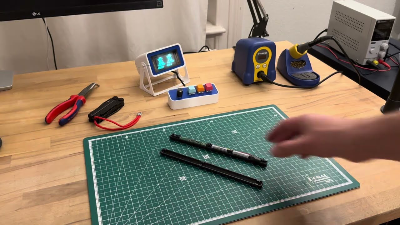
In this video you can see five different spells being recorded:
Replay mode
This is the default mode in which spellcaster will live most of its life. Once a spell is cast, it will be compared to previously stored spells. If a good match is found, a vibration pattern is executed and an action will be triggered.
On false positives
The matching algorithm is optimized for something to happen. There is a low threshold for matching spells, and often two or more will be sufficiently matched. This depends on how similar spells are, but the best matching spell will always be selected. The idea is that, when we intentionally cast a spell, the correct one will almost always be selected, instead of -- sometimes -- none. On the other hand, previously unseen spells may trigger a false positive.
This is done to mainly prevent the sorry sight of a full grown adult waving a wand in the air in front of friends and family at a dinner party and nothing happening. Don't ask. A better solution is to further tune the spell matching algorithm to be more robust against these cases, while retaining the precision when the casting is intentional. Another idea is to add an invisible capacitive touch sensor to the handle, which would also allow for much deeper sleep modes. Something to be improved.
Deep sleep mode
If spellcaster is still for 10 seconds, it will enter the lowest power mode at around 65 uA. Most of which goes to the accelerometer, which lies semi-awake in a low power state waiting for movement. This can mostly likely be optimized further. Any movement will wake it up and into replay mode.
Software
There are a few sample firmwares in the repository. They are all written with Nordic's nRF Connect SDK. Most samples are adapted from the SDK's examples.
| Directory | Description |
|---|
code/sclib | Generic spellcaster library. Handles spell casting, storing and signal processing. Used by all other samples. |
code/samples/ble-bthome | Matched spell S trigger a BTHome.io action that is equivalent to S button presses. This can then be used by Home Assistant automations. |
code/samples/ble-hid | spellcaster pairs with your computer via BLE. Matched spell S trigger a BLE-HID action that simulates a key press following the configurable keymap. |
code/samples/zigbee | Matched spells trigger Zigbee Cluster actions that can be used by Home Assistant automations. Unfortunately, the Zigbee specs don't define magic wand clusters, so the spellcaster.py ZHA Quirk needs to be installed. With it, matched spell on slot S appears to be a "dim light" command with step S. Yikes! (And it's not even the worst hack around here). |
code/samples/ble-dump | Dumps raw accel & gyro spells over BLE. The client.py connects to spellcaster and dumps the data to a file. This is how I collected the data for tuning the spell matching without cables getting in the way. |
Building the samples
These are standard nRF Connect SDK projects with Zephyr RTOS, and the official docs apply. The b-parasite project uses a similar setup with a generic library and different samples, and the Wiki contains more details and alternatives.
Flashing the samples
The samples are flashed with ARM's usual SWD. The official docs also apply. The only caveat is the custom, slim 6-testpoint SWD pins on the PCB. It also happens to the the exact same as described in the b-parasite Wiki.
Data analysis
The data/ directory contains a bunch of Jupyter notebooks I used to tune the spell matching and some of the raw collected data.
3D printed case

The 3dprint/ directory contains the STEP files for a 3D printed case. It's okay-ish, but could use some love. The 3D printed springs lose some tension after a while, and so do the clamps that hold both halves together. On the bright side, there's no glue nor screws involved. You can watch a video of the full assembly process here.
License
Hardware
spellcaster hardware © 2023 by rbaron is licensed under Creative Commons Attribution-ShareAlike 4.0 International (CC BY-SA 4.0). See deed.
Software
Software in this repository is licensed under the MIT license. See LICENSE_SOFTWARE.


