2 layers51.7 × 80.7 mm
ESPHome MultiPresence
PennyLekas/ESPHome_MultiPresence
A ESPHome presence sensor with mmWave radar, PIR motion, light, temperature, humidity, and pressure
48 parts2GPL-3.0

 rawrrudy/kibo2
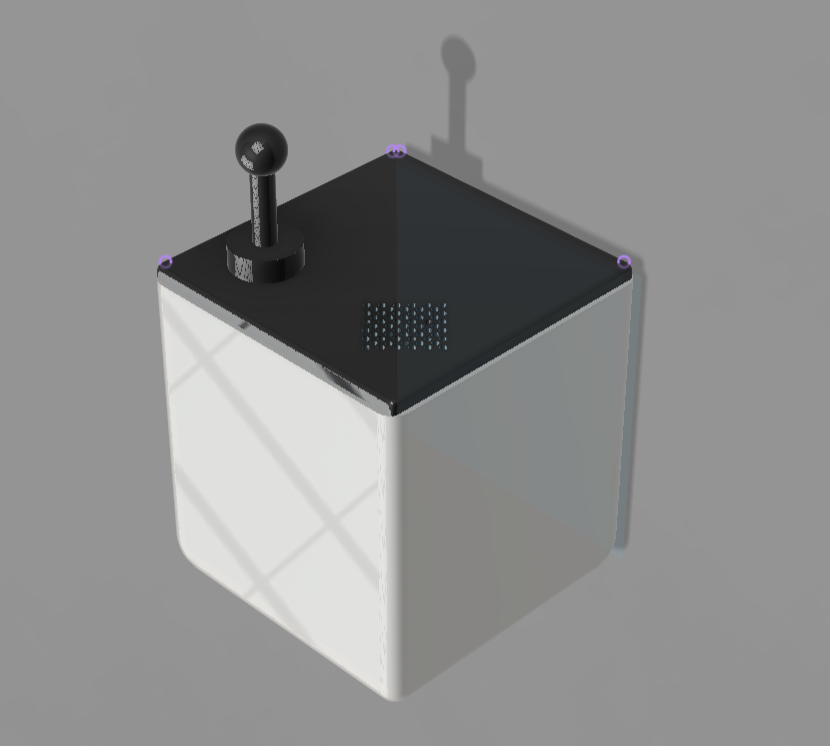
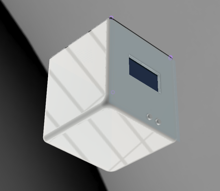
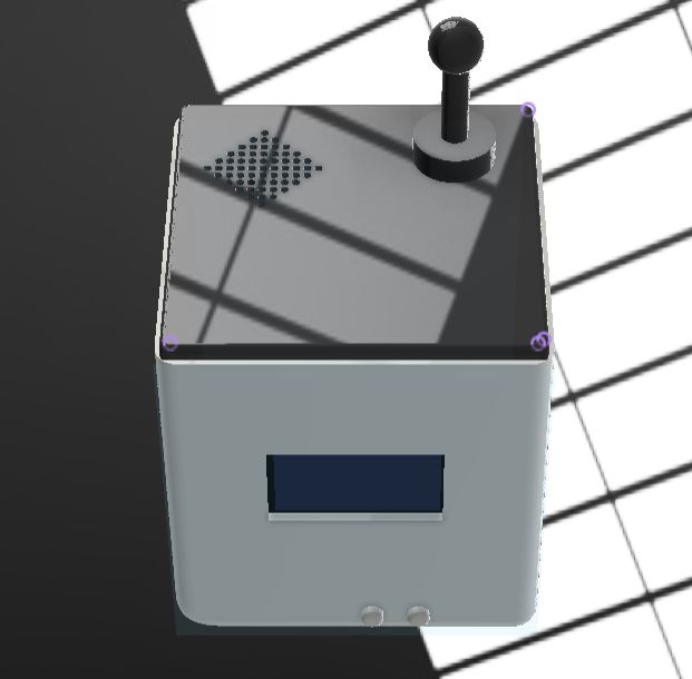
Say hi to Kibo! Kibo is a desktop companion robot that recognizes human emotions and responds through movement, sounds and visual feedback!
Kibo V1 is an open-source printed circuit board by rawrrudy, from the rawrrudy/kibo repository on GitHub, published under the MIT licence. It is a 2-layer board of 58.5 × 55 mm with 22 parts on 84 nets, routed with 242 tracks and 3 vias.
It is built around the ESP32-WROOM-32, TLV75533PDBV and SS8050. Its parts include 8 capacitors, 6 resistors, 3 ICs, 2 transistors and 2 switches. It belongs with the ESP32 boards of this library.


Say hi to Kibo! Kibo is a desktop companion robot that recognizes human emotions and responds through movement, sounds and visual feedback!
This project was created for Horizons | Hack Club!
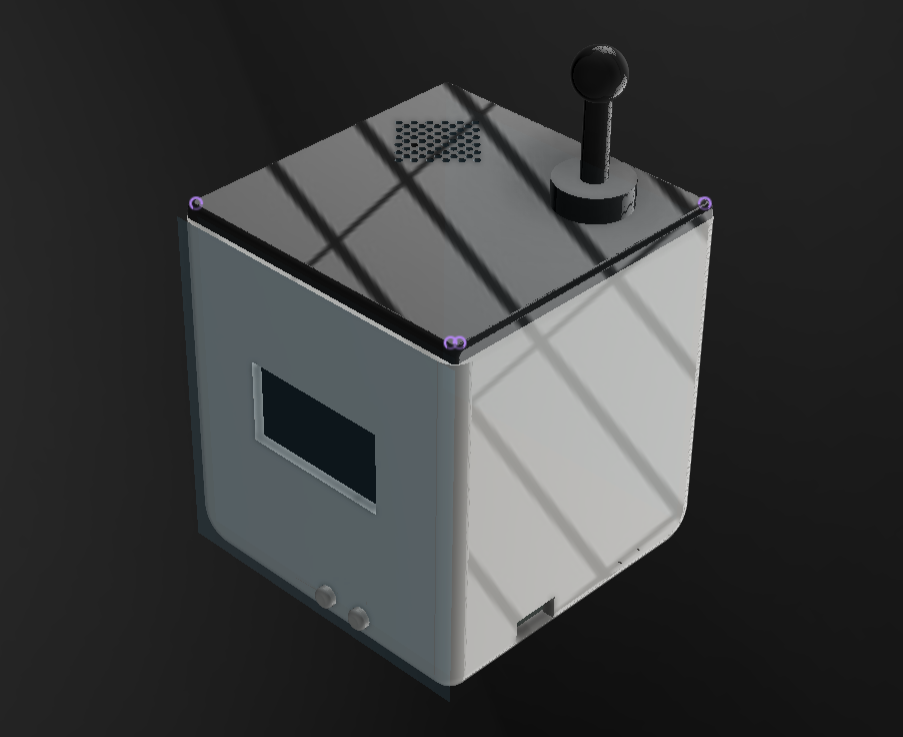
So the primary idea behind Kibo is for it to be a desktop companion that emotionally connects to people (especially teenagers) and keeps a track of their moods and emotions and to sort of create a register of behavioral patterns. It is designed to understand human emotions and respond through sound and visual feedback.
It has a lot of sensors and a custom designed PCB that pieces together Kibo!

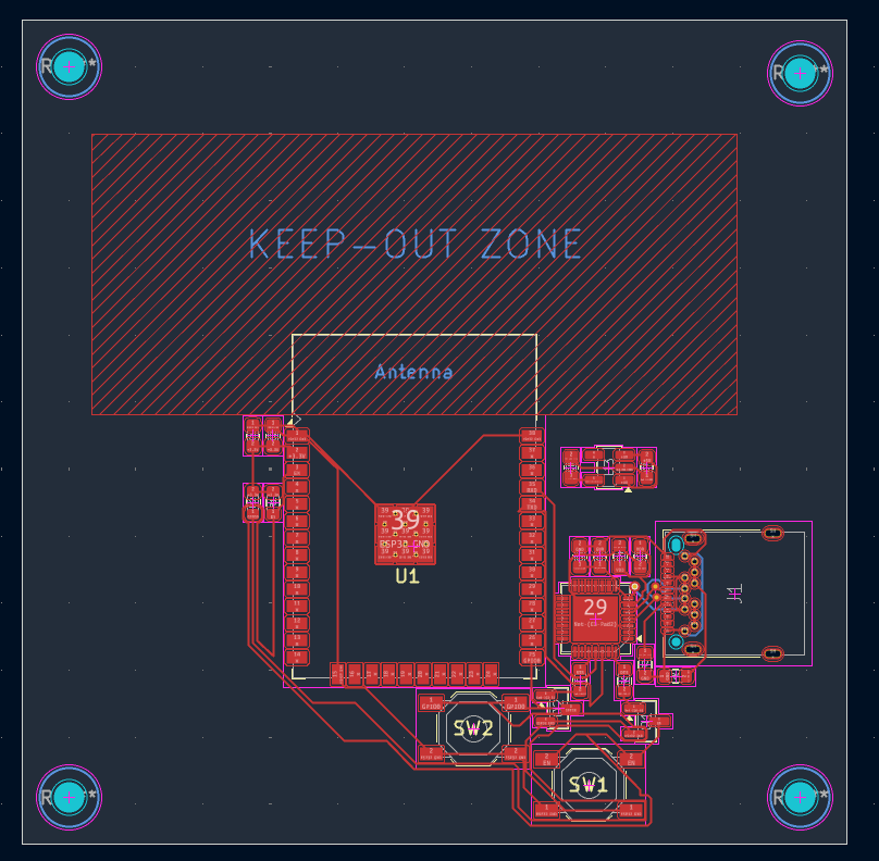
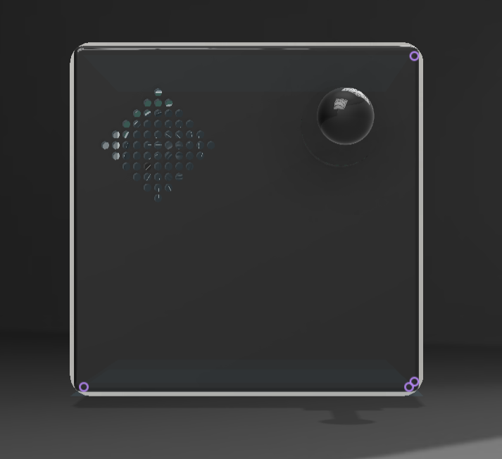
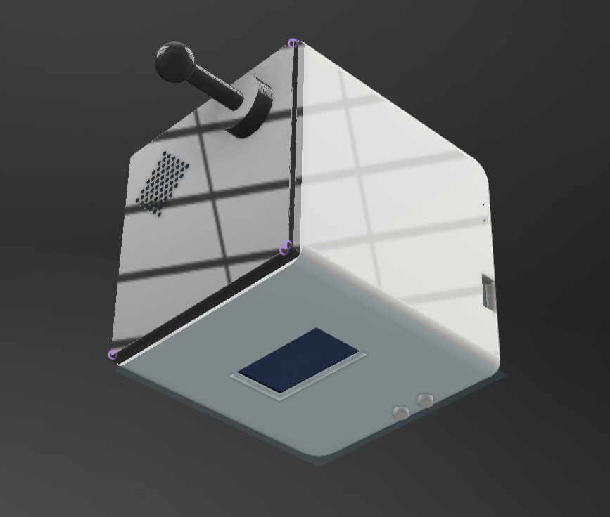
Image of the PCB used in Kibo!
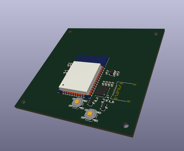
3D view of the PCB used in Kibo!
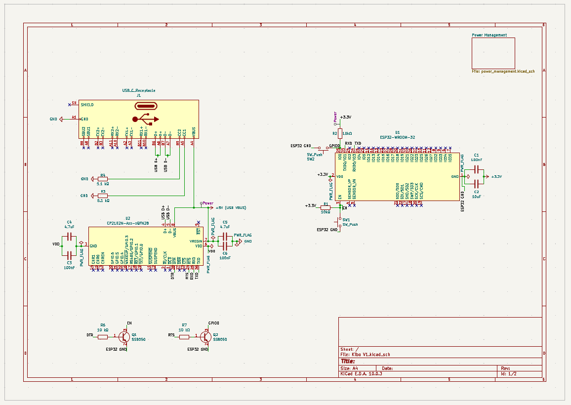
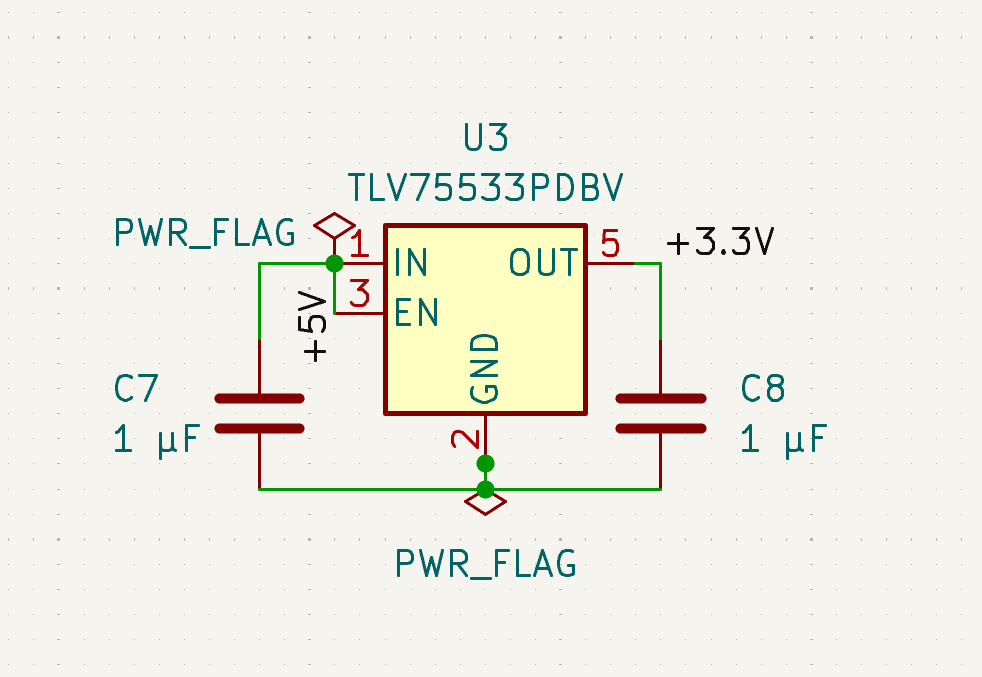
Schematic diagram of Kibo!
Note: At the time of writing, this is the first version/prototype of Kibo. After getting my project reviewed and accepted, I plan on adding much more features and the firmware will change based on those factors!
Please check the BOM before building this project!
Connect all the electronic components of Kibo according to the schematic.
| Component | Connection / Function |
|---|---|
| ESP32 WROOM 32 | Main controller |
| CP2102N | USB to UART communication |
| USB-C | Power + programming |
| SS8050 ×2 | Automatic boot |
| RESET button | ESP32 reset |
| BOOT button | ESP32 bootloader mode |
| Speaker | Audio Output |
| Sensors/peripherals | Connected according to the final Kibo wiring |
Refer to the PCB schematic and hardware documentation in the hardware directory for detailed connections and pin assignments.
cd backendpython -m venv venvvenv\Scripts\activatesource venv/bin/activatepip install -r requirements.txtuvicorn app.main:app --reloadcd frontendnpm installnpm run devhelpstatus
info
versionwifi scan|
|
|
|
|
|
|
I would like to thank-
and the entire team at Horizons | Hack Club to conduct such an awesome experience!
This project is licensed under the MIT License. See the LICENSE file for more details.
| Qty | Value | Footprint | References |
|---|---|---|---|
| 3 | 100nF | Capacitor_SMD:C_0603_1608Metric | C1, C3, C6 |
| 2 | 1 µF | Capacitor_SMD:C_0603_1608Metric | C7, C8 |
| 2 | 10 kΩ | Resistor_SMD:R_0603_1608Metric | R6, R7 |
| 2 | 10kΩ | Resistor_SMD:R_0603_1608Metric | R1, R2 |
| 2 | 4.7uF | Capacitor_SMD:C_0603_1608Metric | C4, C5 |
| 2 | 5.1 kΩ | Resistor_SMD:R_0603_1608Metric | R3, R4 |
| 2 | SS8050 | Package_TO_SOT_SMD:SOT-23 | Q1, Q2 |
| 2 | SW_Push | Button_Switch_SMD:SW_SPST_TL3342 | SW1, SW2 |
| 1 | 10uF | Capacitor_SMD:C_0603_1608Metric | C2 |
| 1 | CP2102N-Axx-xQFN28 | Package_DFN_QFN:QFN-28-1EP_5x5mm_P0.5mm_EP3.35x3.35mm | U2 |
| 1 | ESP32-WROOM-32 | RF_Module:ESP32-WROOM-32 | U1 |
| 1 | TLV75533PDBV | Package_TO_SOT_SMD:SOT-23-5 | U3 |
| 1 | USB_C_Receptacle | Connector_USB:USB_C_Receptacle_Amphenol_12401548E4-2A | J1 |
PennyLekas/ESPHome_MultiPresence
A ESPHome presence sensor with mmWave radar, PIR motion, light, temperature, humidity, and pressure

ChrisMeletis/satelight_pcb
A repository containing all the printed circuit boards for the SateLight project.


Fluepke/Fluepdot
Project for controlling Annax flipdot panels used by the Berliner Verkehrsbetriebe

ampnics/CAN-to-WiFi-Converter-Dongle-
CAN to WiFi Converter PCB using ESP32! This step-by-step tutorial covers schematic creation, PCB layout, and best practices for signal integrity. Perfect for automotive and IoT applications!

alextrical/ESP32-Sentinel-Kinetic-Wireless-Dongle
ESP8266 based Re-implementation of the Vent-Axia Sentinel Kinetic Wired Remote Controller without a Display

cnlohr/esp32_tracker
DO NOT USE THIS PROJECT - ESP32 Tracker with the TS4231

moksh-pcb-design/ESP32-WROOM-Development-Board
Custom ESP32-WROOM-32 Development Board designed in KiCad 10 featuring USB Type-C, CH340C USB-UART interface, AMS1117 power regulation and auto-programming circuitry.
It measures 58.5 × 55 mm and has 2 copper layers, 1.6 mm thick.
22 parts, built around the ESP32-WROOM-32, TLV75533PDBV and SS8050. The full list of its parts is on this page, with links to each part's symbol and footprint where PCBKit's library has them.
From the rawrrudy/kibo repository on GitHub, at the commit this page was made from: the board is hardware/pcb/Kibo V1.kicad_pcb and its schematic hardware/schematic/Kibo V1.kicad_sch. PCBKit opens the board in the browser, with nothing to install.
Its repository publishes it under the MIT licence: you may reuse it on that licence's terms (keep the author's notice, and for a copyleft licence share your changes alike).