Skip to the content
PCBKitNew board
2 layers25.5 × 70.6 mmCaliper mod, the printed circuit board in 3D

This project involves modifying inexpensive digital calipers purchased from AliExpress by replacing the internal CR44 battery with a custom PCB. The modification adds the following features:

Size
25.5 × 70.6 mm
Copper layers
2
Thickness
0.8 mm
Parts
19
Nets
11
Pads
45
Tracks, vias
69, 22
Pours
1
Routed
Yes
KiCad
KiCad 9.0 (file 20241229)
Created
30 Dec 2025
Updated
30 Dec 2025

Overview

Caliper mod is an open-source printed circuit board by RasmusKoit, from the RasmusKoit/caliper-mod repository on GitHub. It is a 2-layer board of 25.5 × 70.6 mm with 19 parts on 11 nets, routed with 69 tracks and 22 vias.

Its parts include 4 capacitors, 4 resistors, 2 ICs, 1 diode and 1 connector.

README

README.md

Modded Digital Calipers with USB-C Rechargeable Battery

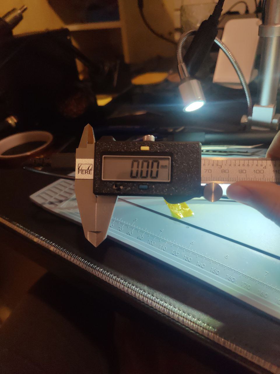
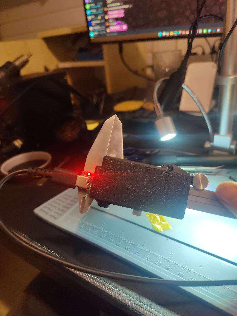
Calipers FrontCalipers Back

This project involves modifying inexpensive digital calipers purchased from AliExpress by replacing the internal CR44 battery with a custom PCB. The modification adds the following features:

  • USB-C Charging: A USB-C connector is added to charge a LiPo battery.
  • LiPo Battery Integration: A LiPo battery powers the calipers, eliminating the need for disposable batteries.
  • Voltage Conversion: The LiPo battery voltage is converted to 1.5V to match the calipers' power requirements.

This upgrade makes the digital calipers rechargeable and more convenient to use.

Features

  • Custom PCB Design: A custom PCB was created to integrate the USB-C charging circuit and voltage regulator.
  • Eco-Friendly: Reduces waste by eliminating the need for disposable CR44 batteries.
  • Enhanced Usability: Rechargeable functionality ensures the calipers are always ready for use.
  • Easy to modify: The design allows for straightforward installation into existing calipers or to other voltages by changing the regulator.
  • Custom 3D Printed Case: A 3D printed case is designed to house the modified calipers and the custom PCB. Making it easy to add the extra wires and battery. MakerWorld link

Future Improvements

  • Add battery level indicators.
  • Break away tab to use in other projects to minimize the size of the PCB.

Assembly Instructions

Bill of Materials

  • 4x M2x12mm screws
  • 2x M2x4mm screws
  • 1x Caliper-mod PCB
  • 1x LiPo Battery (150mAh or similar) (max height 3mm)
  • 1x Switch with 3-5mm slider (612-EG1271A)
  • 1x Cheap digital calipers from AliExpress with the following case is the one I tested: alt text
  • Some glue (optional to secure the switch)
  • Some double-sided tape for the battery
  • 3D printed caliper case (optional but recommended)

Schematic and PCB Design

PCBs were ordered from ATAPCB.

ATAPCB logo

Just upload the provided production zip file to their website for manufacturing.

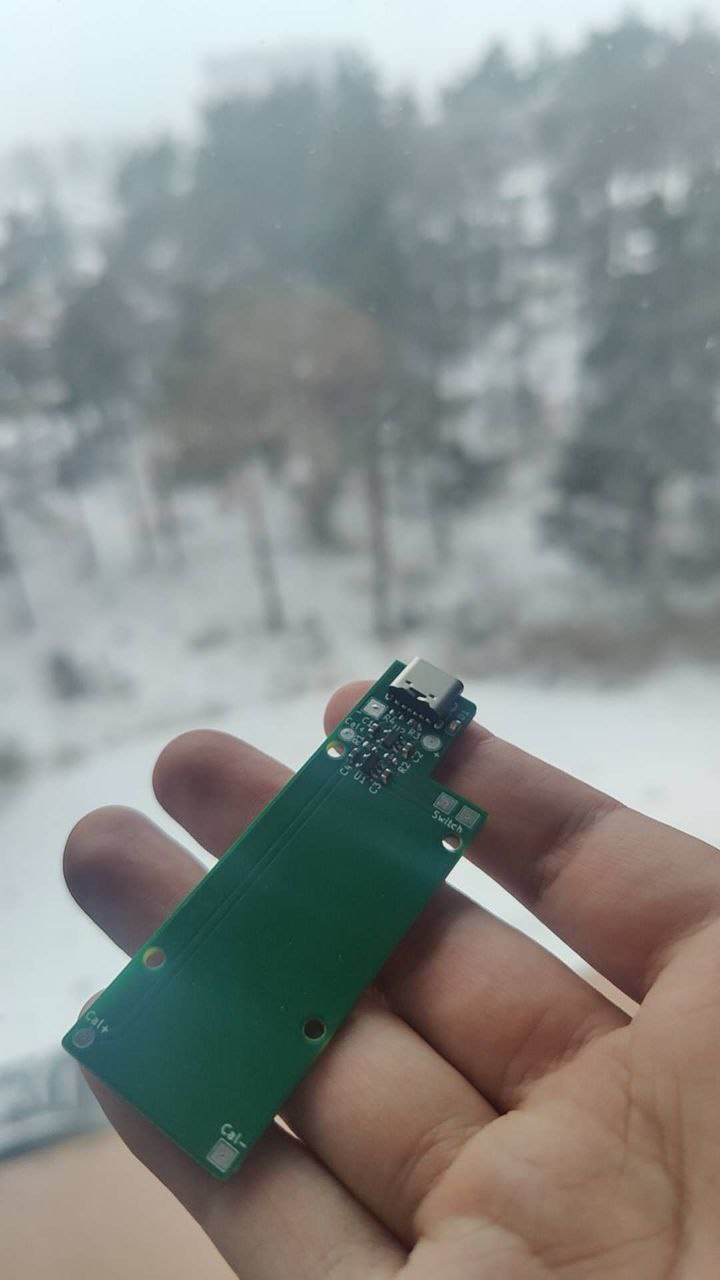
Assembled PCB

The schematic and PCB for this project were designed using KiCad. Below is the Bill of Materials (BOM) for the components used:

ReferenceValueDatasheetQtyManufacturer Part NumberMouser Part Number
C1, C24.7uF~2LMK107BJ475KA-T963-LMK107BJ475KA-T
C3, C41uF~2LMK107B7105KA-T963-LMK107B7105KA-T
D1LED~1LTST-C190KRKT859-LTST-C190KRKT
J1USB_C_PowerOnly_6PUSB Type-C Datasheet1USB4125-GF-A-0190640-USB4125-GF-A-190
R156k~1CRG0603F56K279-CRG0603F56K
R21.5k~1CRG0603F1K5279-CRG0603F1K5
R3, R45.1k~2CRG0603F5K1279-CRG0603F5K1
SW1SW_Push~1EG1271A612-EG1271A
U1LDK130-15_SOT23_SOT353LDK130 Datasheet1STLQ015M15R511-STLQ015M15R
U2MCP73831-2-OTMCP73831 Datasheet1MCP73831T-2ACI/OT579-MCP73831T-2ACIOT

Notes

  • Ensure all components are soldered correctly and oriented as per the schematic.
  • Use a multimeter to verify connections and check for shorts after assembly.
  • The LDO will not turn on until the switch pads are shorted/connected.

3D Printed Case

The 3D printed case is designed to house the modified calipers and the custom PCB. You can download the Bambu 3mf files from MakerWorld link. Print the case using PLA or PETG for durability.

Installation Steps

  1. Remove the existing CR44 battery from the calipers.
  2. Remove back stickers and screws to open the caliper casing.
  3. Gently extract the internal components.
  4. Print out the new caliper case, this is technically optional but recommended for a better fit. MakerWorld link
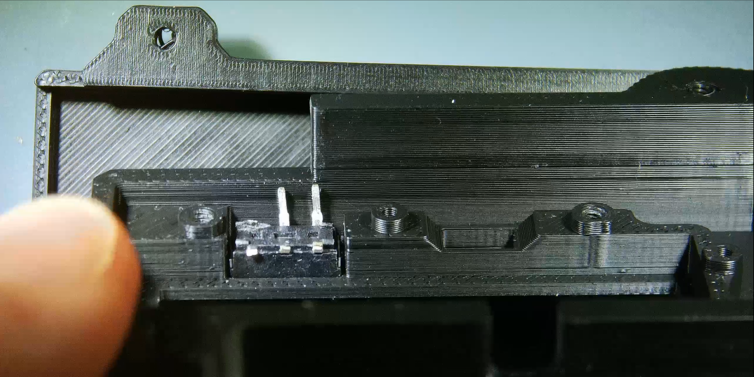
  5. Install the switch into the new case. switch install
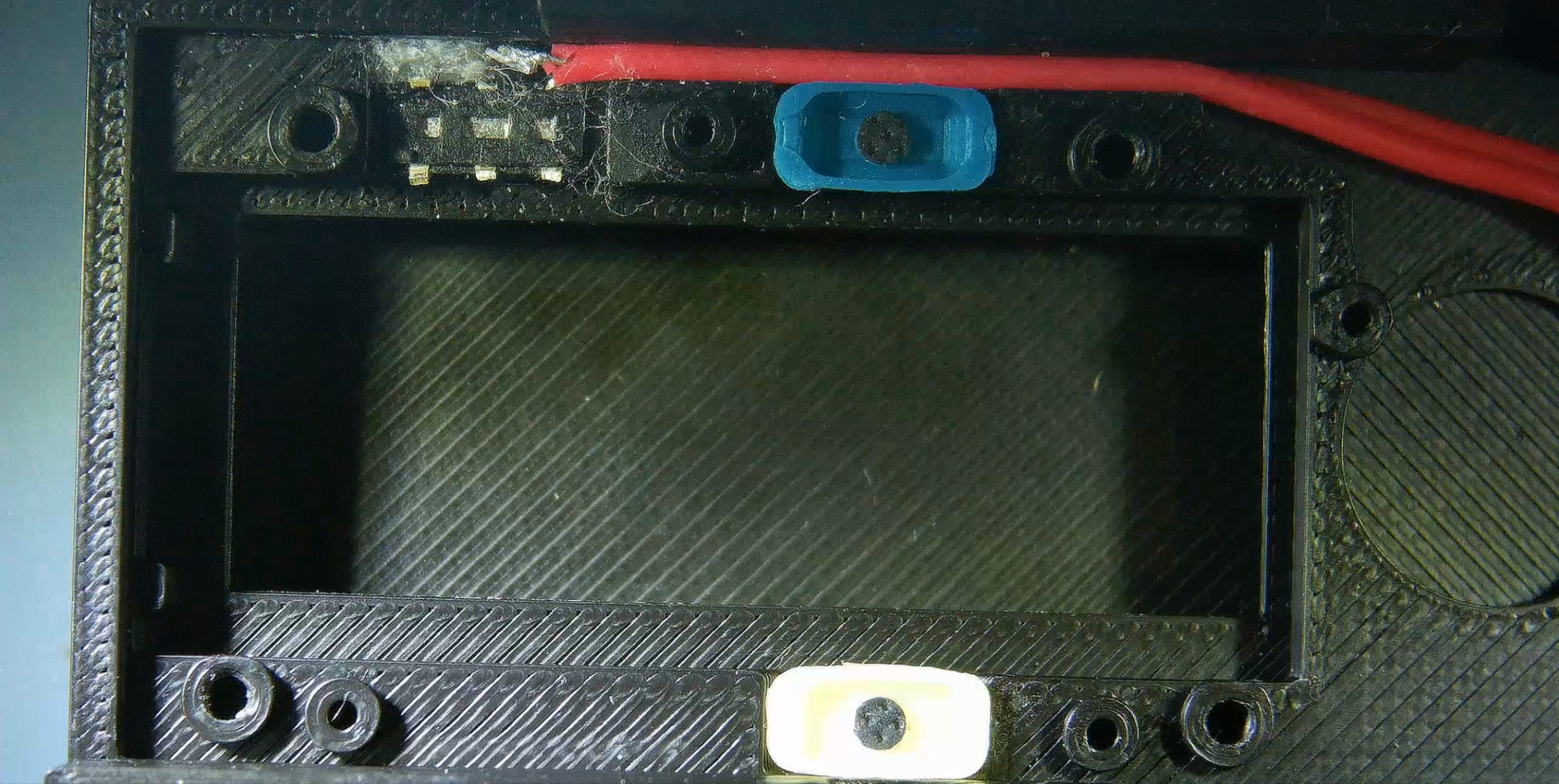
  6. Install units button into the new case.
  7. Install the reset button into the new case. buttons installed
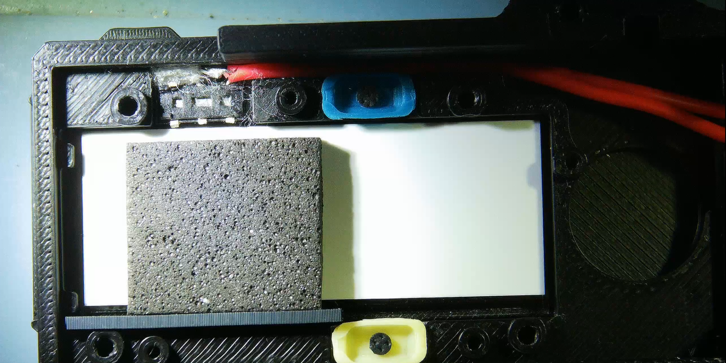
  8. Install the screen into the new case. screen install
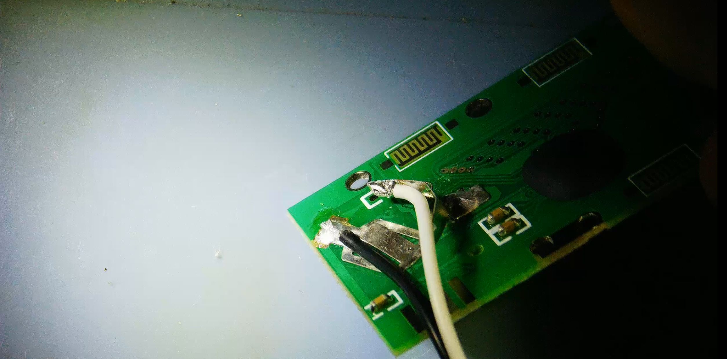
  9. Solder wires from the PCB to the caliper's original battery contacts (observe polarity). Battery Contacts soldered
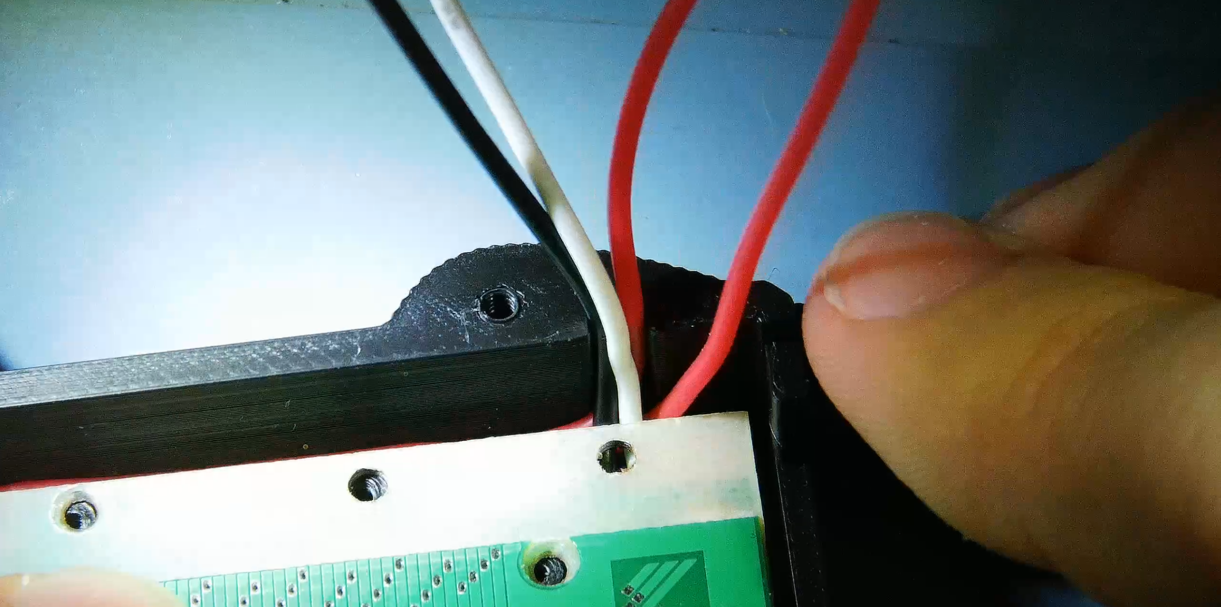
  10. Place the caliper PCB into the case, ensuring the wires are routed out from the dedicated side gap, alternatively you can route them through the USB measurement hole/Battery compartment if not using the 3D printed case. Wires routed and PCB placed
  11. Secure the original PCB to the new case.
  12. Add the metal scroll wheel back to the calipers.
  13. Place the calipers into the new case
  14. Add the caliper-mod PCB into the new case, ensure the holes line up.
  15. Secure the caliper-mod PCB and caliper with M2x12mm screws.
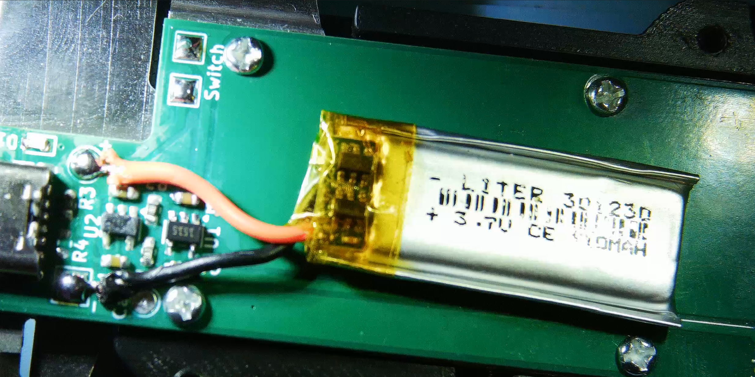
  16. Solder the battery to the + and - pads on the caliper-mod PCB, righet next to the USB-C connector. battry install
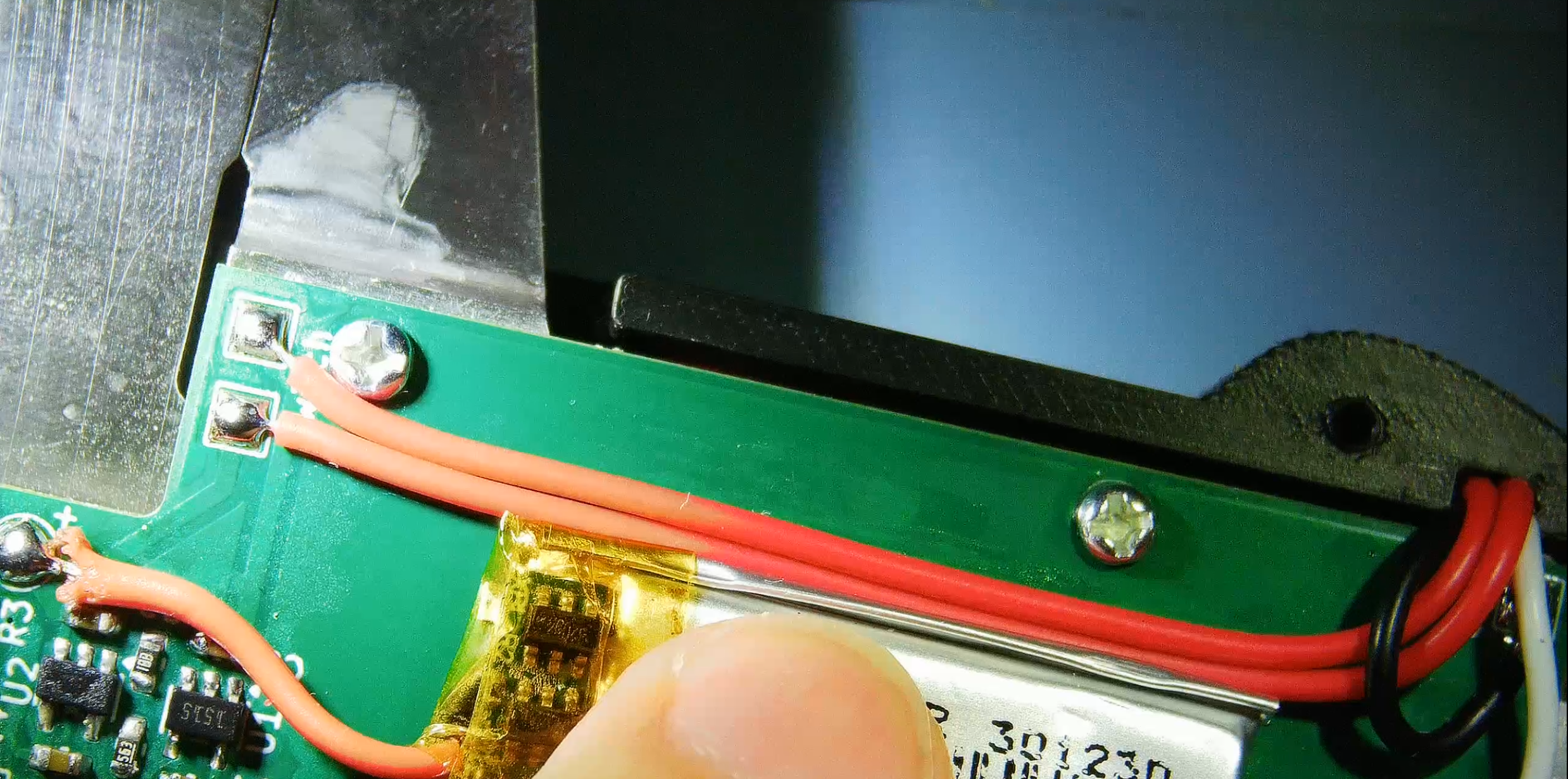
  17. Solder the switch wires to the switch pads on the caliper-mod PCB. Switch wires
  18. Solder the caliper's original battery contacts wires to the Cal+ (OUT+) and Cal- (OUT-) pads on the caliper-mod PCB.
    • Technically the Cal- is just GND and the Cal+ pad is duplicated to add more soldering options.
  19. Close the caliper case and secure it with the M2x4mm screws.
  20. Install back the screen cover.

Parts

19
QtyValueFootprintReferences
3TestPointTestPoint:TestPoint_Pad_2.0x2.0mmTP1, TP2, TP4
21uFCapacitor_SMD:C_0603_1608MetricC3, C4
24.7uFCapacitor_SMD:C_0603_1608MetricC1, C2
25.1kResistor_SMD:R_0603_1608MetricR3, R4
2TestPointTestPoint:TestPoint_Pad_D2.0mmTP3, TP7
11.5kResistor_SMD:R_0603_1608MetricR2
156kResistor_SMD:R_0603_1608MetricR1
1LDK130-15_SOT23_SOT353Package_TO_SOT_SMD:SOT-23-5U1
1LEDLED_SMD:LED_0603_1608MetricD1
1MCP73831-2-OTPackage_TO_SOT_SMD:SOT-23-5U2
1TestPointTestPoint:TestPoint_Pad_2.5x2.5mmTP6
1TestPointTestPoint:TestPoint_Pad_D2.5mmTP5
1USB_C_Receptacle_PowerOnly_6PConnector_USB:USB_C_Receptacle_GCT_USB4125-xx-x-0190_6P_TopMnt_HorizontalJ1

Questions

How big is the Caliper mod PCB?

It measures 25.5 × 70.6 mm and has 2 copper layers, 0.8 mm thick.

What parts does the Caliper mod use?

19 parts. The full list of its parts is on this page, with links to each part's symbol and footprint where PCBKit's library has them.

Where can I download the Caliper mod KiCad files?

From the RasmusKoit/caliper-mod repository on GitHub, at the commit this page was made from: the board is PCB/caliper-mod.kicad_pcb and its schematic PCB/caliper-mod.kicad_sch. PCBKit opens the board in the browser, with nothing to install.

Can I use the Caliper mod design in my own project?

Its repository states no licence, so its author keeps all rights: ask RasmusKoit before reusing the design.

Similar boards

  • 2 layers43.9 × 27.7 mmTcd1304-4v, the printed circuit board in 3D

    Tcd1304-4v

    OpnTec/open-spectrometer-hardware

    Open source VIS spectrometer

    19 parts1.5k
  • 2 layers50 × 60 mmDebate Device, the printed circuit board in 3D

    Debate Device

    hackclub/OnBoard

    💡 Join 1,000 teenagers and make your first PCB with a $100 grant!

    19 parts915
  • 2 layers102.9 × 96.7 mmISA adapter, the printed circuit board in 3D

    ISA adapter

    polpo/picogus

    Emulation of ISA sound cards and CD-ROM on Raspberry Pi Pico (GUS, SB/Adlib, MPU-401, Tandy, CMS, Panasonic CD-ROM) with USB mouse/joystick support

    19 parts805
  • 2 layers60 × 39 mmPs2usb, the printed circuit board in 3D

    Ps2usb

    rasteri/HIDman

    Adapting USB devices to work on old computers

    19 parts432
  • 2 layers70.1 × 43.2 mmIaq device, the printed circuit board in 3D

    Iaq device

    nkitanov/iaq_board

    IAQ Board is a DIY (Do-It-Yourself) device for measuring internal air quality

    19 parts396
  • 2 layers80 × 80 mmGB BRK CPU G1, the printed circuit board in 3D

    GB BRK CPU G1

    Gekkio/gb-hardware

    Game Boy -related custom hardware by gekkio

    19 parts379CC-BY-4.0
  • 2 layers25.4 × 25.4 mmIna169, the printed circuit board in 3D

    Ina169

    Ardumower/ardumower

    Develop an open source robotic lawn mower (HW+SW reference platform)

    19 parts282
  • 2 layers58.4 × 28.6 mmNew rele, the printed circuit board in 3D

    New rele

    zmaker/arduino_cookbook

    gli sketch del nuovo progetto Arduino Cookbook e dei video di YouTube

    19 parts269