4 layers155.7 × 147.6 mm

 ramalamadingdong/pcb-agent4
Design a PCB end to end with an agent: CSV source of truth, idempotent build passes, containerized KiCad+Freerouting, and checks that run on the fab output.
Unoq power shield is an open-source printed circuit board by ramalamadingdong, from the ramalamadingdong/pcb-agent repository on GitHub, published under the GPL-3.0 licence. It is a 4-layer board of 53.3 × 68.6 mm with 56 parts on 48 nets, routed with 272 tracks and 60 vias.
It is built around the R11, R16 and INA226AIDGSR, with the TPS54331DDAR, BSS138LT1G and AO4407A among its other parts. Its parts include 19 resistors, 10 capacitors, 9 connectors, 5 transistors and 3 diodes.


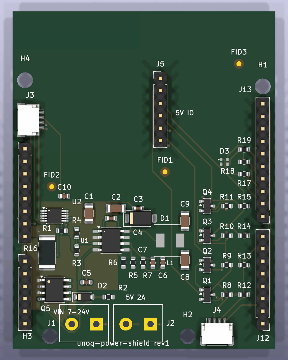 | 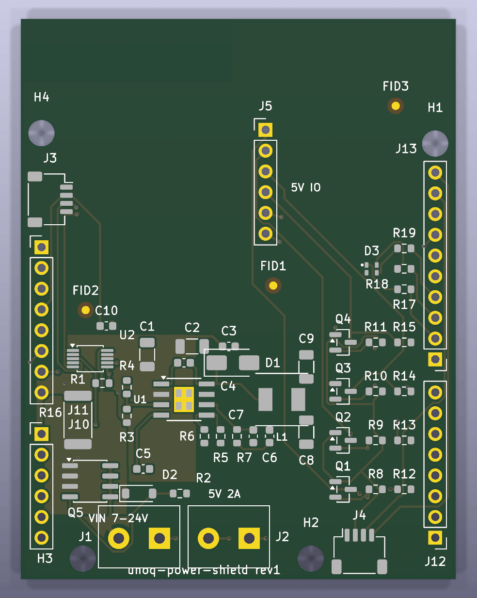 |
| Populated — every footprint with its 3D model. The four edge strips and J5 are drawn as plain male pin headers because that is what the footprint's model is; the real parts are stacking headers — female sockets on top, long tails passing down into the UNO Q — and they ship DNP (see below), so an assembled board arrives with those pads bare. | Bare — the PCB the fab builds from the gerbers: four-layer copper, mask, silk, and the three X2-tagged fiducials the assembler's vision system needs. |
Status: UNBUILT. No physical board of this design has been fabricated or powered on yet. Until one has, treat this as a reference for exercising the pipeline, not a verified design.
The design has passed its pre-order gates (2026-08-30): routed with
0 unconnected and 0 clearance violations across 5 identical DRC
runs, validate_gerbers 14/0, ERC clean, every BOM line in stock. The 17
residual DRC items are all form-factor or courtyard-graze artifacts,
individually explained in the ledger in rev-1-plan.md.
Passing gates is not the same as working hardware — the UNBUILT warning
above stands until a board has been powered on.
The stacking headers ship DNP — the assembled board cannot plug into anything until you solder a stacking header set into the four plated hole strips. Any classic Arduino R3 stacking kit fits: SparkFun PRT-11417 or Adafruit #85, about $2. This is deliberate: assembly houses don't stock stacking headers, and a flush-soldered normal header would make the shield unstackable.
The example board for this repo — the design a first-time user builds before trusting the pipeline with their own board. If this builds, routes, checks, and comes back from the fab working, the pipeline works. That is all it proves: it says nothing about whether any other design is right, and it is not a product.
A shield for the Arduino UNO Q (classic UNO outline, stacking headers):
Design record: rev-1-plan.md — every requirement cited to Arduino's own documents, every part checked against the JLCPCB library, every number with its arithmetic shown. Rules: board.toml.
Each board.toml rule exists here for a visible physical reason:
| Rule | Why it's real on this board |
|---|---|
| thermal vias | the buck's exposed pad is its only real heatsink |
| power trace width | VIN carries up to 4 A; IPC-2221 sets the number |
| mounting holes | all four fixed by the UNO pattern — extracted from Arduino's own drill file |
| planes | solid ground under a switching converter |
| keepout | the UNO Q's Wi-Fi antenna is directly under the board's top-left corner — copper there detunes it |
| fiducials, X2-tagged | assembly needs them, and untagged ones are invisible to gerber-level checking |
| Supply | Result |
|---|---|
| USB-C only | UNO Q runs; shield 5 V rail is off (needs VIN) — by design |
| VIN only | everything runs; the Q is powered through its VIN pin |
| both | fine — the Q diode-ORs internally; the shield never drives the 5 V or 3V3 header pins |
The UNO Q facts in this design — pinout, electrical limits, mechanical coordinates, antenna location — come from Arduino's official documents and CAD files for the UNO Q (ABX00162), © Arduino SA, licensed CC BY-SA 4.0: datasheet, full pinout, schematics, and fab data, copies in docs/datasheets/. The antenna keepout and hole/header coordinates were extracted from the gerber and NC-drill files Arduino publishes there. This example's own design files are MIT like the rest of the repo; the CC BY-SA attribution above covers what was derived from Arduino's documents.
| Qty | Value | Footprint | References |
|---|---|---|---|
| 4 | BSS138LT1G | SOT-23 | Q1, Q2, Q3, Q4 |
| 4 | MountingHole_3.2mm | MountingHole_3.2mm | H1, H2, H3, H4 |
| 3 | Fiducial_pcb-agent | Fiducial_pcb-agent | FID1, FID2, FID3 |
| 2 | 22uF 25V | C_1206_3216Metric | C8, C9 |
| 2 | 4.7uF 50V | C_1206_3216Metric | C1, C2 |
| 2 | Qwiic | JST_SH_SM04B-SRSS-TB_1x04-1MP_P1.00mm_Horizontal | J3, J4 |
| 1 | 10mR 3W | R_2512_6332Metric | R1 |
| 1 | 10uH | SWPA6045S | L1 |
| 1 | 5V IO | PinHeader_1x06_P2.54mm_Vertical | J5 |
| 1 | 5V OUT | KF301_5.0_2P | J2 |
| 1 | AO4407A | SOIC-8_3.9x4.9mm_P1.27mm | Q5 |
| 1 | BZT52C12 | D_SOD-123 | D2 |
| 1 | C10 | C_0603_1608Metric | C10 |
| 1 | C3 | C_0603_1608Metric | C3 |
| 1 | C4 | C_0603_1608Metric | C4 |
| 1 | C5 | C_0603_1608Metric | C5 |
| 1 | C6 | C_0603_1608Metric | C6 |
| 1 | C7 | C_0603_1608Metric | C7 |
| 1 | INA226AIDGSR | MSOP-10_3x3mm_P0.5mm | U2 |
| 1 | R10 | R_0603_1608Metric | R10 |
| 1 | R11 | R_0603_1608Metric | R11 |
| 1 | R12 | R_0603_1608Metric | R12 |
| 1 | R13 | R_0603_1608Metric | R13 |
| 1 | R14 | R_0603_1608Metric | R14 |
| 1 | R15 | R_0603_1608Metric | R15 |
| 1 | R16 | R_0603_1608Metric | R16 |
| 1 | R17 | R_0603_1608Metric | R17 |
| 1 | R18 | R_0603_1608Metric | R18 |
| 1 | R19 | R_0603_1608Metric | R19 |
| 1 | R2 | R_0603_1608Metric | R2 |
| 1 | R3 | R_0603_1608Metric | R3 |
| 1 | R4 | R_0603_1608Metric | R4 |
| 1 | R5 | R_0603_1608Metric | R5 |
| 1 | R6 | R_0603_1608Metric | R6 |
| 1 | R7 | R_0603_1608Metric | R7 |
| 1 | R8 | R_0603_1608Metric | R8 |
| 1 | R9 | R_0603_1608Metric | R9 |
| 1 | SS34 | D_SMA | D1 |
| 1 | TPS54331DDAR | TI_SO-PowerPAD-8 | U1 |
| 1 | UNO ANALOG | PinHeader_1x06_P2.54mm_Vertical | J11 |
| 1 | UNO D0-D7 | PinHeader_1x08_P2.54mm_Vertical | J12 |
| 1 | UNO D8-SCL | PinHeader_1x10_P2.54mm_Vertical | J13 |
| 1 | UNO PWR | PinHeader_1x08_P2.54mm_Vertical | J10 |
| 1 | VIN 7-24V | KF301_5.0_2P | J1 |
| 1 | XL-1615RGBC-RF | XL1615RGBC | D3 |
It measures 53.3 × 68.6 mm and has 4 copper layers, 1.6 mm thick.
56 parts, built around the R11, R16, INA226AIDGSR and TPS54331DDAR. The full list of its parts is on this page, with links to each part's symbol and footprint where PCBKit's library has them.
From the ramalamadingdong/pcb-agent repository on GitHub, at the commit this page was made from: the board is examples/unoq-power-shield/unoq-power-shield.kicad_pcb and its schematic examples/unoq-power-shield/unoq-power-shield.kicad_sch. PCBKit opens the board in the browser, with nothing to install.
Its repository publishes it under the GPL-3.0 licence: you may reuse it on that licence's terms (keep the author's notice, and for a copyleft licence share your changes alike).


cc90202/DCC-esp32
DCC command station for ESP32-C6 — NMRA-compliant model railroad controller in Rust


changgeruoxiao/hagent
一块 STM32H743ZIT6(LQFP144, Cortex-M7 @ 480MHz)最小系统核心板,以及生成它的全自动化 EDA 流水线: