2 layers110.5 × 54.1 mm

 rainerhassel/MisterClippy3
Clipping Detector Module
MisterClippy is an open-source printed circuit board by rainerhassel, from the rainerhassel/MisterClippy repository on GitHub, published under the CC-BY-SA-4.0 licence. It is a 2-layer board of 30.2 × 109.2 mm with 73 parts on 54 nets, routed with 568 tracks and 91 vias.
It is built around the TL072, LM393 and BC547. Its parts include 28 resistors, 18 capacitors, 9 connectors, 5 ICs and 5 diodes. It belongs with the audio and music boards of this library.


Clipping Detector Module
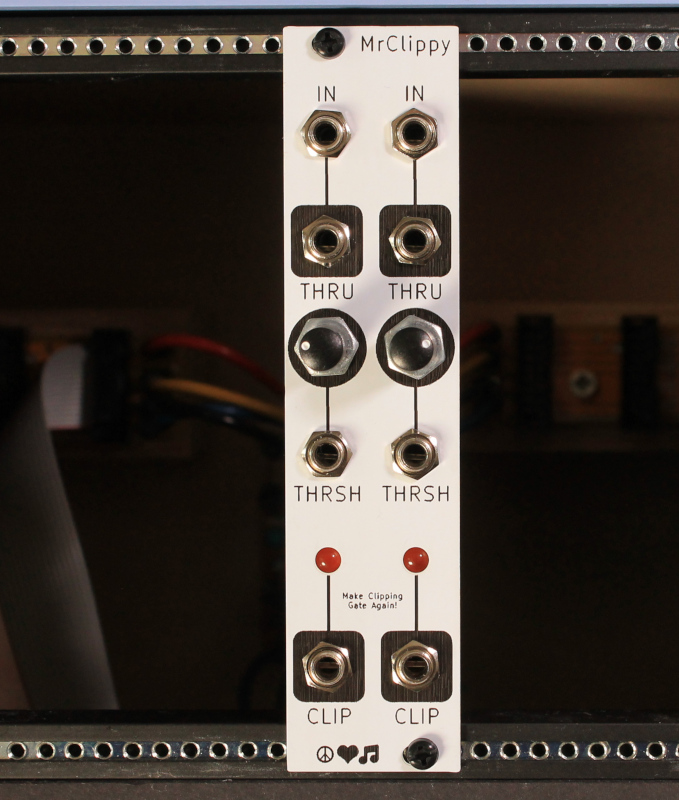
This project uses symbols from the moPsy-KiCad-resources.

This work is licensed under a Creative Commons Attribution-ShareAlike 4.0 International License.
BY: Patrick Pickel (@rainerhassel) and Stefan Haun (@penguineer)
See LICENSE.txt for details.
Using moPsy-KiCad-resources by Stefan Haun (mail@tuxathome.de).
| Qty | Value | Footprint | References |
|---|---|---|---|
| 15 | 100n | Capacitor_THT:C_Disc_D4.3mm_W1.9mm_P5.00mm | C1, C2, C3, C4, C5, C6, C7, C8, C9, C12, C13, C14, C16, C17, C18 |
| 6 | 470k | Resistor_THT:R_Axial_DIN0207_L6.3mm_D2.5mm_P7.62mm_Horizontal | R4, R7, R9, R10, R11, R12 |
| 4 | 1k | Resistor_THT:R_Axial_DIN0207_L6.3mm_D2.5mm_P7.62mm_Horizontal | R5, R8, R25, R26 |
| 4 | 22k | Resistor_THT:R_Axial_DIN0207_L6.3mm_D2.5mm_P7.62mm_Horizontal | R13, R15, R19, R20 |
| 4 | 2k2 | Resistor_THT:R_Axial_DIN0207_L6.3mm_D2.5mm_P7.62mm_Horizontal | R14, R16, R21, R22 |
| 4 | 4k7 | Resistor_THT:R_Axial_DIN0207_L6.3mm_D2.5mm_P7.62mm_Horizontal | R23, R24, R27, R28 |
| 3 | 100k | Resistor_THT:R_Axial_DIN0207_L6.3mm_D2.5mm_P7.62mm_Horizontal | R3, R6, R18 |
| 3 | 10u | Capacitor_THT:CP_Radial_D4.0mm_P1.50mm | C10, C11, C15 |
| 3 | 1N5817 | Diode_THT:D_DO-41_SOD81_P7.62mm_Horizontal | D3, D4, D5 |
| 3 | LM393 | Package_DIP:DIP-8_W7.62mm | U1, U4, U5 |
| 2 | 100k | mopsy:Potentiometer_Befaco_12mm_Single_Vertical | RV1, RV2 |
| 2 | 10k | Potentiometer_THT:Potentiometer_Piher_PT-10-V10_Vertical | RV3, RV4 |
| 2 | 1M | Resistor_THT:R_Axial_DIN0207_L6.3mm_D2.5mm_P7.62mm_Horizontal | R1, R2 |
| 2 | Audio In | mopsy:Jack_3.5mm_QingPu_WQP-PJ398SM_Vertical_CircularHoles_Centered | J1, J2 |
| 2 | BC547 | Package_TO_SOT_THT:TO-92_HandSolder | Q1, Q2 |
| 2 | FerriteBead | mopsy:FBeadL4D4 | FB1, FB2 |
| 2 | Input | mopsy:Jack_3.5mm_QingPu_WQP-PJ398SM_Vertical_CircularHoles_Centered | J5, J6 |
| 2 | LED | LED_THT:LED_D3.0mm | D1, D2 |
| 2 | Output Gate | mopsy:Jack_3.5mm_QingPu_WQP-PJ398SM_Vertical_CircularHoles_Centered | J7, J8 |
| 2 | TL072 | Package_DIP:DIP-8_W7.62mm | U2, U3 |
| 2 | Through | mopsy:Jack_3.5mm_QingPu_WQP-PJ398SM_Vertical_CircularHoles_Centered | J3, J4 |
| 1 | 47k | Resistor_THT:R_Axial_DIN0207_L6.3mm_D2.5mm_P7.62mm_Horizontal | R17 |
| 1 | PWR | Connector_PinHeader_2.54mm:PinHeader_2x08_P2.54mm_Vertical | J9 |
It measures 30.2 × 109.2 mm and has 2 copper layers, 1.6 mm thick.
73 parts, built around the TL072, LM393 and BC547. The full list of its parts is on this page, with links to each part's symbol and footprint where PCBKit's library has them.
From the rainerhassel/MisterClippy repository on GitHub, at the commit this page was made from: the board is PCB/misterclippy.kicad_pcb and its schematic PCB/clip_cv.kicad_sch. PCBKit opens the board in the browser, with nothing to install.
Its repository publishes it under the CC-BY-SA-4.0 licence: you may reuse it on that licence's terms (keep the author's notice, and for a copyleft licence share your changes alike).


keeos-io/ogham
Ogham — a dual-voice bytebeat synthesizer for Eurorack. Firmware (MIT) and hardware (CC BY-SA 4.0).

sverrham/diy-smu
DIY Source Measurement Unit, four quadrant powersupply and ?.? digit volt/current meter.

fberni21/taller-circuitos
FIUBA - Electrónica - Taller de Diseño de Circuitos Electrónicos


