
4 layers106 × 110 mm
RearCircuitBoard 10
ssbingo/samba-solar-track
Samba Solar Track – Solarnachführung mit Sturmschutz: Handbuch, Platine und Gehäuse für den Nachbau (10,1-Zoll-Version)
329 parts

A budget PLC-like board for controlling 24V DC equipment.
PoppyIO is an open-source printed circuit board by Rahix, from the Rahix/Poppy-Logic-Controller repository on GitHub. It is a 2-layer board of 102 × 86 mm with 255 parts on 195 nets, routed with 1,395 tracks and 279 vias.
It is built around the PCA9538PW, 74HC14 and ULN2003AD, with the PTS645, SKL14 and SS14 among its other parts. Its parts include 89 resistors, 34 diodes, 33 capacitors, 16 fuses and 13 ICs. It belongs with the RP2040 boards of this library.


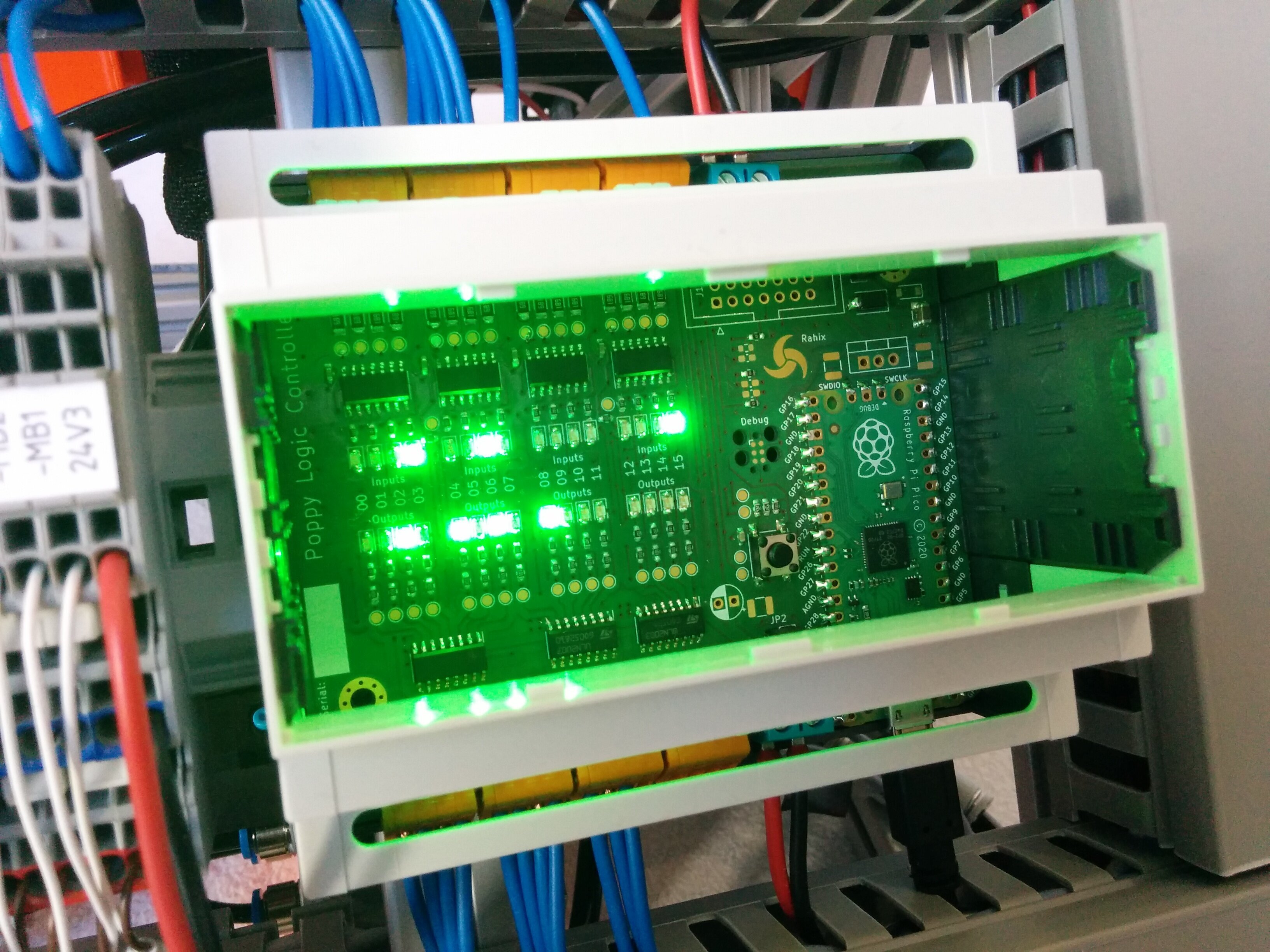
The Poppy Logic Controller is a budget PLC (Programmable Logic Controller). Importantly, it is only an I/O board without any PLC programming environment (so far). It isn't designed to be super robust but instead to use minimal components while still staying compatible with standard industrial 24V DC control systems.
I release the Poppy Logic Controller as open hardware in hopes that others who need a cheap solution for controlling industrial 24V DC equipment find it useful. This is not a commercially viable PLC alternative.
If you want to know more about the background of this project and details of the design, you might be interested in the blog post I wrote about it: Poppy Logic Controller
Learn more about sinking/sourcing I/O here and here or from my blog-post about this project.
J12
header.Rendered versions of the schematic and BOM can be found here:
Supplier for almost all parts of this project was Reichelt Elektronik (no affiliation or sponsorship here, purely personal choice). I've tried reconstructing the BOM with all the Reichelt SKUs so you can painlessly get all you need from one place if you so desire. There is a column in the BOMs linked above with all the information you need.
Beyond the PCB's BOM, you will need a few more components. After all, you probably want the nice feeling of mounting your controller on a DIN-rail, don't you?
APRA-NORM 449-360-65 (Reichelt APRA DB6 OBK)APRA-NORM 449-360-12 (Reichelt
APRA 449-360-12). Also available in other colors.JUMPER 2,54 SW)In the design files, you'll find the latest revision D. I suggest using that one although it is not exactly the version I have built. My (2) boards are built from revision B with one populated like revision C and one populated like revision D. You can read the changelog for details of the differences.
This repository contains a bare-bones firmware in Rust and MicroPython to get started. Or, if you have a background in automation, you can program the Poppy Logic Controller in ST (Structured Text) using the IEC 61131-3 firmware. Check the READMEs for more info on that:
If you need a different microcontroller, you can drop the Raspberry Pi Pico and
instead solder the J12 header. You can then connect whatever controller you
desire and use the I²C bus (and interrupt lines) to interact with the I/O.
If you want to build your own but you are unsure or you have questions about anything, feel free to contact me to get it sorted out!
Hardware/) are licensed under the
CERN-OHL-W.Firmware-*/) are licensed under
MIT.| Qty | Value | Footprint | References |
|---|---|---|---|
| 36 | TestPoint_Small | TestPoint:TestPoint_Pad_D1.5mm | TP1, TP2, TP10, TP11, TP12, TP13, TP14, TP15, TP16, TP17, TP18, TP19, TP20, TP21, TP22, TP23 +20 |
| 32 | 1k | Resistor_SMD:R_0603_1608Metric | R13, R14, R15, R16, R25, R26, R27, R28, R37, R38, R39, R40, R49, R50, R51, R52 +16 |
| 32 | Green | LED_SMD:LED_0805_2012Metric_Pad1.15x1.40mm_HandSolder | D10, D11, D12, D13, D14, D15, D16, D17, D18, D19, D20, D21, D22, D23, D24, D25 +16 |
| 20 | 10k | Resistor_SMD:R_0603_1608Metric | R3, R4, R69, R70, R74, R75, R76, R77, R78, R79, R80, R81, R82, R83, R84, R85 +4 |
| 16 | 1n | Capacitor_SMD:C_0805_2012Metric | C8, C9, C10, C11, C12, C13, C14, C15, C16, C17, C18, C19, C20, C21, C22, C23 |
| 16 | 3.3k 250mW | Resistor_SMD:R_1206_3216Metric | R5, R6, R7, R8, R17, R18, R19, R20, R29, R30, R31, R32, R41, R42, R43, R44 |
| 16 | 30V 300mA | Fuse:Fuse_1210_3225Metric_Pad1.42x2.65mm_HandSolder | F1, F2, F3, F4, F5, F6, F7, F8, F9, F10, F11, F12, F13, F14, F15, F16 |
| 16 | 820 250mW | Resistor_SMD:R_1206_3216Metric | R9, R10, R11, R12, R21, R22, R23, R24, R33, R34, R35, R36, R45, R46, R47, R48 |
| 10 | 100n | Capacitor_SMD:C_0603_1608Metric_Pad1.08x0.95mm_HandSolder | C4, C5, C6, C7, C24, C25, C26, C27, C28, C29 |
| 9 | SolderJumper_2_Bridged | Jumper:SolderJumper-2_P1.3mm_Bridged_RoundedPad1.0x1.5mm | JP3, JP4, JP5, JP6, JP7, JP8, JP9, JP10, JP11 |
| 8 | WAGO 233-504 | PoppyLogicController:WAGO_233-204 | J1, J2, J3, J4, J5, J6, J7, J8 |
| 4 | 10u | Capacitor_SMD:C_1210_3225Metric | C1, C30, C32, C33 |
| 4 | 74HC14 | Package_SO:SOIC-14_3.9x8.7mm_P1.27mm | U9, U10, U11, U12 |
| 4 | PCA9538PW | Package_SO:TSSOP-16_4.4x5mm_P0.65mm | U2, U3, U4, U5 |
| 3 | 0R | Resistor_SMD:R_0603_1608Metric | R1, R2, R73 |
| 3 | ULN2003AD | Package_SO:SOIC-16_3.9x9.9mm_P1.27mm | U6, U7, U8 |
| 2 | 4.7k | Resistor_SMD:R_0603_1608Metric_Pad0.98x0.95mm_HandSolder | R71, R72 |
| 2 | MountingHole_Pad | MountingHole:MountingHole_3.2mm_M3_Pad_Via | H1, H2 |
| 2 | TestPoint | TestPoint:TestPoint_Pad_D1.5mm | TP37, TP38 |
| 2 | ~ | Capacitor_SMD:C_0603_1608Metric_Pad1.08x0.95mm_HandSolder | C2, C3 |
| 2 | ~ | Connector_PinHeader_2.54mm:PinHeader_1x02_P2.54mm_Vertical | JP1, JP2 |
| 1 | 10u | Capacitor_THT:CP_Radial_D5.0mm_P2.50mm | C31 |
| 1 | Conn_02x07_Odd_Even | Connector_IDC:IDC-Header_2x07_P2.54mm_Vertical | J12 |
| 1 | LM78xx | PoppyLogicController:TO-220-3_Vertical_Clearance | U13 |
| 1 | MKDS-1,5-2-5.08 | TerminalBlock_Phoenix:TerminalBlock_Phoenix_MKDS-1,5-2-5.08_1x02_P5.08mm_Horizontal | J10 |
| 1 | PTS645 | Button_Switch_SMD:SW_SPST_PTS645 | SW1 |
| 1 | Pico | RPi_Pico:RPi_Pico_SMD_TH | U1 |
| 1 | SKL14 | Diode_SMD:D_SOD-123 | D1 |
| 1 | SS14 | Diode_SMD:D_SMA | D2 |
| 1 | SYM_Rahix | PoppyLogicController:SYM_Rahix | SYM1 |
| 1 | TC2030-IDC | Connector:Tag-Connect_TC2030-IDC-FP_2x03_P1.27mm_Vertical | J11 |
The 249 most common of 255 parts.
It measures 102 × 86 mm and has 2 copper layers, 1.6 mm thick.
255 parts, built around the PCA9538PW, 74HC14, ULN2003AD and PTS645. The full list of its parts is on this page, with links to each part's symbol and footprint where PCBKit's library has them.
From the Rahix/Poppy-Logic-Controller repository on GitHub, at the commit this page was made from: the board is Hardware/PoppyIO/PoppyIO.kicad_pcb and its schematic Hardware/PoppyIO/PoppyIO.kicad_sch. PCBKit opens the board in the browser, with nothing to install.
Its repository states no licence, so its author keeps all rights: ask Rahix before reusing the design.
ssbingo/samba-solar-track
Samba Solar Track – Solarnachführung mit Sturmschutz: Handbuch, Platine und Gehäuse für den Nachbau (10,1-Zoll-Version)


RunningJoke/reactionButton
ReactPod: ESP32-C3 reaction buzzers – firmware, Config App (PWA), tools, hardware


