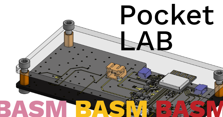
The Pocket Lab is the next-generation approach to science education. Designed by the Bucharest Applied STEAM Museum, it brings scientific exploration into anyone's hands.
Kicad soundcard dev v0 is an open-source printed circuit board by radutolontan, from the radutolontan/BASM_Pocket_Museum repository on GitHub. It is a 4-layer board of 89 × 51 mm with 141 parts on 119 nets, routed with 796 tracks and 176 vias.
It is built around the ESP32-C6-MINI-1U-H4, ES8388 and DM3AT-SF-PEJM5, with the AMS1117-3.3, LSM6DSL and LESD5D5.0CT1G among its other parts. Its parts include 55 resistors, 48 capacitors, 14 diodes, 9 connectors and 6 ICs. It belongs with the ESP32 and RISC-V boards of this library.
The Pocket Lab is the next-generation approach to science education. Designed by the Bucharest Applied STEAM Museum, it brings scientific exploration into anyone's hands. From citizen science projects to fearless exploration (guided or individual), the Pocket Lab illuminates the connections between Science, Technology, Engineering, Art, and Math in the world around us.
Hardware Design
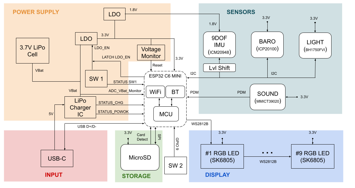
The system is built around an ESP32-C6 MINI microcontroller, which offers:
Powerful processing capabilities
WiFi and Bluetooth connectivity
Excellent integration with accessible codebases through Arduino
The microcontroller collects data from a suite of sensors (9-DOF IMU, light, pressure, audio) and uses a chain of WS2812B RGB LEDs to relay measurements to the user. An on-board microSD card enables data logging and automated grading of student work. Everything is powered by a 3.7V LiPo cell, which is charged using the USB-C connector.
Board ID - Education V0
Power
The power stage is designed for a 500 mAh, 3.7V LiPo cell. Key specifications:
Charger IC: Configured to supply 450 mA in constant-current regime; stops charging when current drops below 150 mA in constant-voltage regime
USB-C Power: Non-negotiated supply limited to 5V @ 500 mA (sufficient for system operation)
Voltage Monitor: Prevents brown-out behavior on the ESP32 when the 3.3V rail drops below 2.9V
Power Latching: A simple circuit enables and latches the LDO through push-button SW1 and an ESP32 GPIO
Display
The display consists of a chain of NeoPixel RGB LEDs organized across three zones:
Mode Display (2 LEDs) - Color-coded indication of the actively displayed quantity:
WHITE → Light
MAGENTA → Sound
YELLOW → Magnetic Field
GREEN → Acceleration
ORANGE → Gyroscope
RED → Air Temperature
BLUE → Air Pressure
Additional device information is also displayed (e.g., battery state: Blinking Orange = Battery Low; Blinking Green = Charging; Blinking Blue = Fully Charged)
Magnitude Display (3-4 LEDs) - Conveys scalar quantities and magnitudes of vector quantities
Direction Display (3 LEDs) - Conveys qualitative Cartesian components (X, Y, Z) for vector quantities
Note: Direction Display is only available in Binary Display Mode (see Software Architecture section)
Sensors
The Pocket Lab EDU V0 includes the following sensors:
Sensor
Measurements
ICM-20948
9-DOF IMU: translational acceleration, rotational velocity, magnetic field strength
ICP-20100
Ambient temperature and air pressure
BH1750FVI
Ambient light intensity
MMICT390200012
Microphone: sound pressure level (dB)
Programming
The MCU can be programmed through Joint Download Boot Mode:
Connect the Pocket Lab to a host computer using a USB-C data cable
Hold down SW2 (labeled "MOD"; connected to GPIO 9)
While holding SW2, press and hold SW1 (labeled "ON/OFF")
Release SW2 while keeping SW1 pressed
Release SW1
The USB-serial connection appears as /dev/ttyACM* (Linux) and allows PlatformIO to flash code to the ESP32-C6.
Software Architecture
The software architecture is built around a FreeRTOS task-based design with a central shared_data_buffer for inter-task communication. Tasks are organized into two tiers:
Task Organization
First-Tier Tasks (Core System)
These tasks are always active and form the foundation of the Pocket Lab operation:
BMSTask - Battery management and power control
SensorTask - Sensor data acquisition and processing
AudioTask - Audio input/output management
DisplayTask - User interface via NeoPixel LEDs
Application-Level Tasks (Feature-Specific)
These tasks are conditionally enabled based on active applications, demos, or features:
SDManager - MicroSD card operations for data logging
EvaluatorTask - Student performance assessment and grading
NetworkTask - WiFi/Bluetooth connectivity features
Responsible for initializing, managing, collecting, and processing sensor data. Pushes each new raw reading to the shared_data_buffer. Uses the SensorHAL virtual layer, as implemented in specific_sensor_HAL, to standardize high-level I/O across all sensors.
Furthermore, note that different sensors are sampled at different rates based on their response characteristics and application requirements.
The task maintains individual timers for each sensor and only reads when that sensor's interval has elapsed, optimizing power consumption and computational load.
States
BOOT - Default state on boot-up; transition to INIT triggered from main.cpp
INIT - Initializes I2C bus for communications to sensors, configures and confirms communications with all sensors
READ - If a sensor is ready to read (based on its individual read_rate_Hz), captures a raw reading and commits it to the latest frame of shared_data_buffer
2. BMSTask
Responsible for managing power delivery to the Pocket Lab. Monitors battery health, informs user about remaining run-time, and handles power-up and shut-down of the entire system.
States
BOOT - Waits until startup timer expires. Prevents accidental power-up if SW 1 is bumped.
STARTUP_LATCH - Configures Charger IC monitoring pins after confirming power is latched.
ACTIVE - Monitors feedback from the Charger IC & Battery Voltage predictions to infer ChargeControllerState:
BATTERY_ONLY - Charger unplugged & battery supplying power
LOW_BATTERY - Charger unplugged & battery supplying power & less than 30 minutes of battery life remaining
CHARGING - Charger connected & battery charging
DONE_CHARGING - Charger connected & supplying power to system (battery charging complete)
SHUTDOWN_PENDING - When SW 1 is pressed to initiate a shut-down, the LDO is un-latched and other tasks are informed to facilitate a clean shut-down.
⚠️ Known Critical Issues
The current BMSTask implementation has several critical issues that will be addressed in future revisions:
Limited voltage monitoring: VBat is only checked when in BATTERY_ONLY state, missing voltage drops during charging or when connected to USB
No automatic low-voltage disconnect: The system does not automatically disconnect power when VBat drops dangerously low, risking deep discharge that could trigger the battery's undervoltage lockout protection
3. AudioTask
Manages audio input and output operations for the Pocket Lab. The AudioTask is responsible for interfacing with the microphone sensor (MMICT390200012) and any future audio peripherals through a Hardware Abstraction Layer (HAL).
This decouples high-level audio processing from hardware-specific implementations, allowing to scale audio I/O in the future.
Like the SensorTask, the AudioTask writes processed audio data (e.g., sound pressure level in dB, frequency analysis) to the shared_data_buffer.
States
BOOT - Default state on boot-up; transition to INIT triggered from main.cpp
INIT - Initializes audio peripherals through the AudioHAL, configures sampling parameters
SAMPLING - Actively captures audio data at the configured sample rate, processes it, and commits results to shared_data_buffer
IDLE - Audio acquisition paused (e.g., during low-power modes or when no audio display is active)
4. DisplayTask
Manages the primary user feedback tool, the chain of NeoPixels. A push-button (SW 2 - display mode button) is debounced and used to cycle through DisplayStates. The current DisplayState is color-coded into the Mode Display.
States
BOOT - Default state on boot-up; transition to INIT triggered from main.cpp
INIT - Initializes the RGB LED strip and displays a color code for the GIT SHA (used to confirm proper code version is running)
DISPLAY_XX - Pulls the latest value for the XX quantity from shared_data_buffer. Updates the Magnitude Display and Mode Display to reflect the measurement.
The DisplayTask supports two distinct visualization modes selected at boot time by holding (or not holding) the display mode button:
Visualization Modes - VU
VU mode provides a classic "volume unit" meter visualization reminiscent of analog audio equipment. In this mode, scalar measurements are displayed as a horizontal bar graph using 6 magnitude LEDs. The display shows the normalized percentage of the measurement relative to predefined min/max thresholds for each sensor type.
The magnitude LEDs use a gradient color scheme that transitions smoothly from green (low values) through yellow (mid-range) to red (high values), providing an intuitive visual indication of intensity. The more LEDs that are lit, the closer the measurement is to its maximum threshold. Vector quantities in VU mode display only their magnitude - no directional information is shown.
Visualization Modes - Binary (Integer Encoding)
Binary mode takes a fundamentally different approach by encoding the actual integer value of measurements rather than showing a percentage. This mode provides precise numerical information that can be decoded by reading the LED colors, making it particularly useful for debugging and data verification.
The system uses 4 magnitude LEDs to encode 12-bit values (0-4095) using a novel 3-bit-per-LED color encoding scheme:
How Binary Encoding Works:
Each RGB LED encodes 3 bits of information using its individual color channels:
Blue channel = Bit m (LSB for that LED)
Yellow channel = Bit m+1 (middle bit)
Red channel = Bit m+2 (MSB for that LED)
The LEDs are arranged from left to right, with LED #1 (leftmost) showing bits 0-2, LED #2 showing bits 3-5, LED #3 showing bits 6-8, and LED #4 (rightmost) showing bits 9-11. This arrangement means that more LEDs being lit indicates a larger magnitude.
Color Combinations: The 3 bits per LED create 8 possible states (0-7), each displayed as a distinct color:
Before encoding, sensor readings are multiplied by sensor-specific scaling factors (defined as BINARY_MAG_ORDER_* constants) to convert floating-point measurements into integer values. For example, temperature is multiplied by 10, so 25.3°C becomes 253, while pressure is multiplied by 10, converting 101.32 kPa to 1013 (then clamped to 4095). Note that acceleration and gyro measurements are very noisy and flicker significantly; the first two bits are masked, effectively rounding every measurement to a multiple of 4.
Direction Display:
Binary mode also displays vector components (X, Y, Z) using 3 dedicated direction LEDs. Each LED shows its component using a color gradient:
RED → Negative values
OFF → Near-zero values (±5% dead zone)
GREEN → Positive values
The intensity of the color fades proportionally with the component's magnitude, providing both sign and strength information.
Application-Level Task Details
5. EvaluatorTask
Responsible for gauging user effort and measuring learning outcomes. The EvaluatorTask owns multiple instances of the abstract base class EvaluatorBase.
EvaluatorBase standardizes I/O across all evaluators, such as DisplaySessionEvaluator (which captures aggregate statistics on sensor data while a specific DisplayTask mode is active). This enables automated grading and feedback for educational activities.
States
BOOT - Default state on boot-up; transition to INIT triggered from main.cpp
INIT - Initializes and confirms appropriate logging is set up for all evaluators
RUNNING - Checks progress on all evaluators and manages access to the SDManager queue for data logging
ERROR - Error handling (not yet implemented)
6. SDManager
Owns operation of the microSD card. It manages access to the storage resource using a separate state machine, handling concurrent read/write requests from multiple tasks.
States
BOOT - Default state on boot-up; transitions to INIT automatically after initializing SD queue
WAIT_FOR_INSERT - Checks and debounces the state of the SD card detect GPIO
MOUNTING - Starts SPI communications, mounts the SD card, and checks SD card metadata
READY - Allows fulfillment of read/write requests in the queue
UNMOUNTING - Unmounts the SD card if removal is detected
ERROR - Error handling (not yet implemented)
7. NetworkTask
Manages WiFi and Bluetooth connectivity features. This task is enabled when network-based applications are active (e.g., data streaming, remote monitoring, firmware updates).
Note: Full NetworkTask implementation details are under development.
SD Card Formatting
In order to read and write to the SD card, it must be formatted to FAT32 with an MBR partition table.
Formatting Instructions (Linux)
Insert the microSD card into a compatible card reader, connect to a Linux machine, and locate the device:
bash
lsblk
Unmount any existing partitions and clear the card (replace /dev/sdX with your device):
The Pocket Lab is the next-generation approach to science education. Designed by the Bucharest Applied STEAM Museum, it brings scientific exploration into anyone's hands.
It measures 89 × 51 mm and has 4 copper layers, 1.61 mm thick.
What parts does the Kicad soundcard dev v0 use?
141 parts, built around the ESP32-C6-MINI-1U-H4, ES8388, DM3AT-SF-PEJM5 and AMS1117-3.3. The full list of its parts is on this page, with links to each part's symbol and footprint where PCBKit's library has them.
Where can I download the Kicad soundcard dev v0 KiCad files?
From the radutolontan/BASM_Pocket_Museum repository on GitHub, at the commit this page was made from: the board is HW_design/DEV_V0/kicad_soundcard_dev_v0/kicad_soundcard_dev_v0/kicad_soundcard_dev_v0.kicad_pcb and its schematic HW_design/DEV_V0/kicad_soundcard_dev_v0/kicad_soundcard_dev_v0/MCU.kicad_sch. PCBKit opens the board in the browser, with nothing to install.
Can I use the Kicad soundcard dev v0 design in my own project?
Its repository states no licence, so its author keeps all rights: ask radutolontan before reusing the design.