4 layers100 × 82.2 mm
4 Bit - Seven Seg Interface
Shaxzodm2611/4-bit-Adder-Interface-Board
A custom PCB designed to mimic the function of a CPU. Entirely made from discrete logic ICs.
128 parts
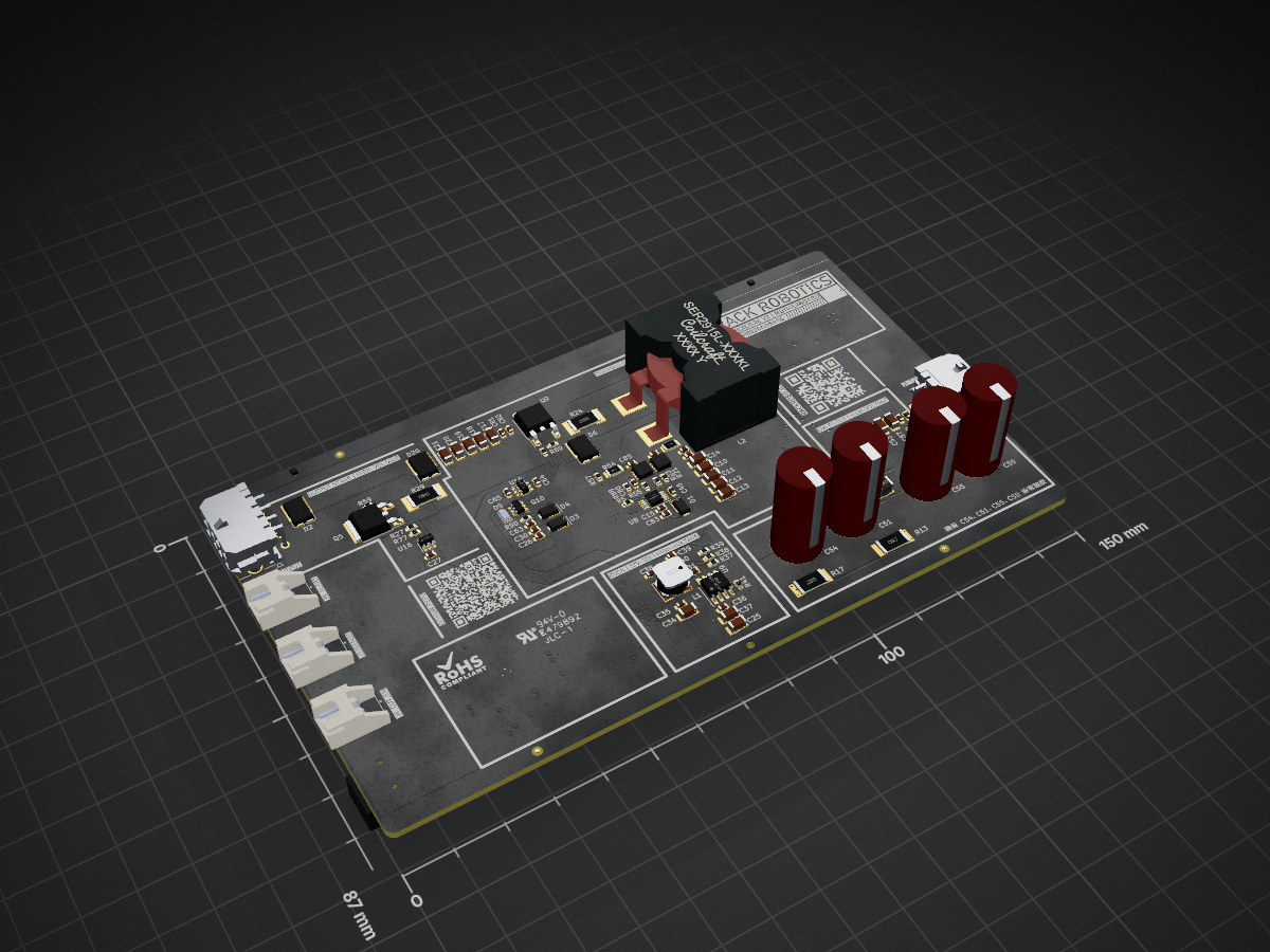
 Rack-Robotics/Powercore-V2.0258
Open-Source wire EDM power supply by Rack Robotics, Inc.
POWERCORE V2.0 MOTHERBOARD is an open-source printed circuit board by Rack-Robotics, from the Rack-Robotics/Powercore-V2.0 repository on GitHub. It is a 6-layer board of 150 × 87 mm with 254 parts on 139 nets, routed with 1,089 tracks and 262 vias.
It is built around the RP2040, LMV358AIDGKRG and IRS10752LTRPBF, with the LM5106MMX/NOPB-JSM, W25Q16JVSNIQ and SN74LVC1G175DCKR(AT) among its other parts. Its parts include 84 resistors, 82 capacitors, 17 ICs, 10 transistors and 9 diodes. It belongs with the power and robots and motor control boards and the RP2040 boards of this library.


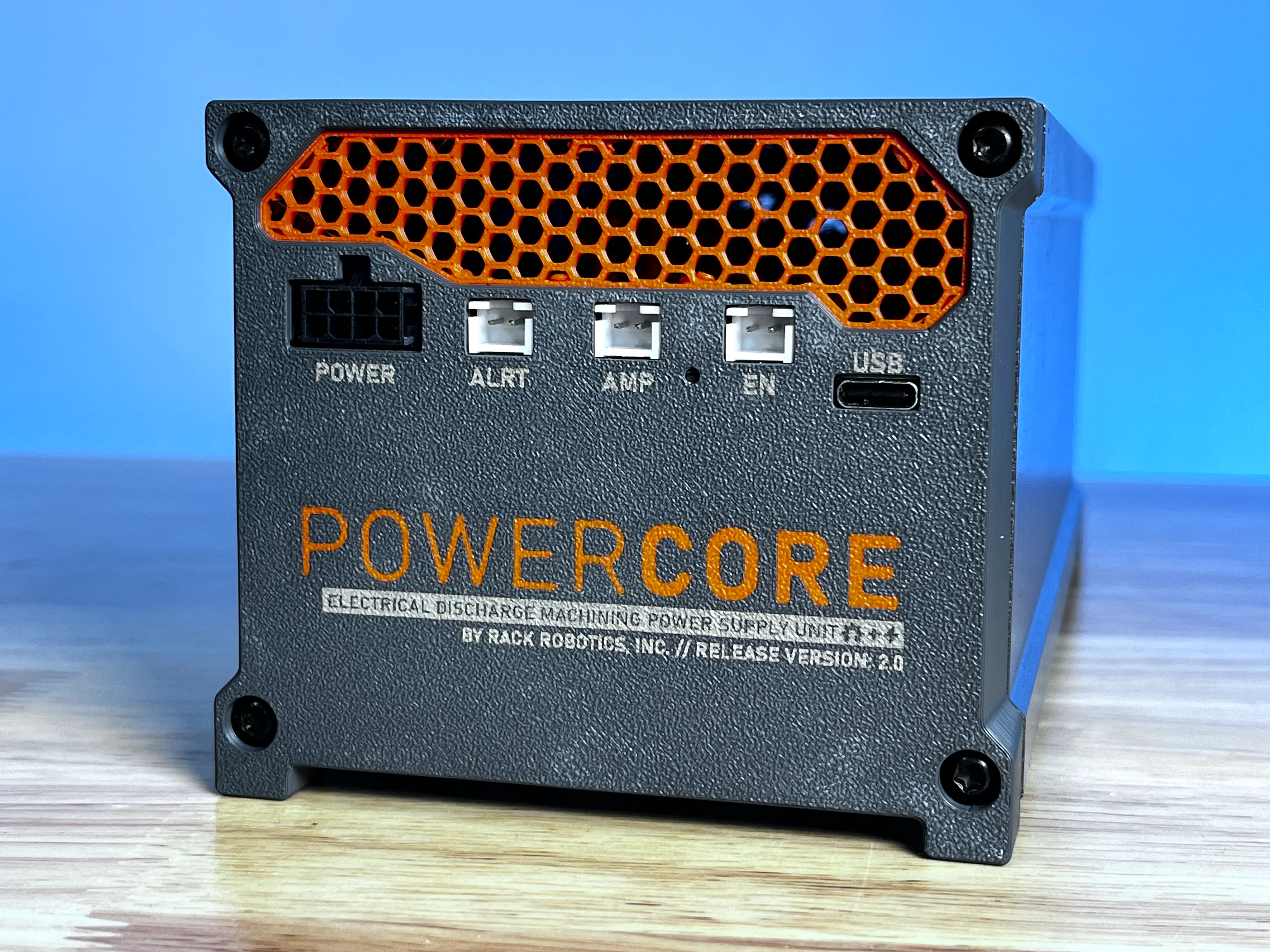
The Powercore V2.0 is an open-source wire EDM (electrical discharge machining) power supply developed by Rack Robotics. It aims to provide a cost-effective and easily replicable solution for wire EDM enthusiasts and professionals. The project includes detailed electrical schematics, firmware, and CAD models. This EDM power supply (spark generator) is intended to be used on custom wire EDM and plunge EDM machines.
This porject is open-source, to encourage collaboration and innovation within the wire EDM community.
| Specification | Value |
|---|---|
| Typical Input Power | 200 Watts |
| Input Voltage | 90-264 VAC |
| Input Frequency | 47-63 Hz |
| Output Voltage | 65 VDC |
| Power Efficiency | Up to 90% |
| PSU Enable Port Voltage Input | 5-36 V |
| Physical Dimensions (XYZ) | 97 x 224 x 79.5 (mm) |
Can this cut X material?
EDM can errode any conductive material. The rate of EDM (Electrical Discharge Machining) machining, also known as spark erosion, is significantly influenced by the thickness, melting point, and density of the material being worked on. Thicker materials generally require more time to erode due to the increased volume that must be removed. Materials with a higher melting point also slow down the machining rate as more energy is required to melt and vaporize the material at the spark point. Additionally, denser materials resist erosion more effectively, requiring more discharge energy to achieve the same material removal rate as less dense materials. Example feedrates are provided bellow, for 0.3 mm diameter zinc-coated, hard brass wire.
| Material | Example Feedrate |
|---|---|
| 3 mm Aluminum | 10 - 28 mm/min |
| 19 mm Aluminum | 1.6 - 4.4 mm/min |
| 4.75 mm Aluminum | 6 - 17 mm/min |
Can the Powercore V2.0 be used for sinker/plunge EDM?
Yes. Gap control is highly recommended for sinker/plunge applications. In plunge/sink EDM, gap control is critical for maintaining machining stability. The gap, or spark gap, is the small space between the electrode and the workpiece. Proper gap control ensures consistent sparking conditions, preventing short circuits and arcing that can damage the workpiece and electrode. It also aids in efficient debris removal, cooling, and flushing of the dielectric fluid, which are essential for maintaining a smooth surface finish and achieving high-accuracy machining. Without precise gap control, the machining process can become unstable, leading to poor-quality results and increased wear on the electrodes. The Powercore V2.0 has a current sense and short alert output port to assist the user in thier implementation.
| Port | Description |
|---|---|
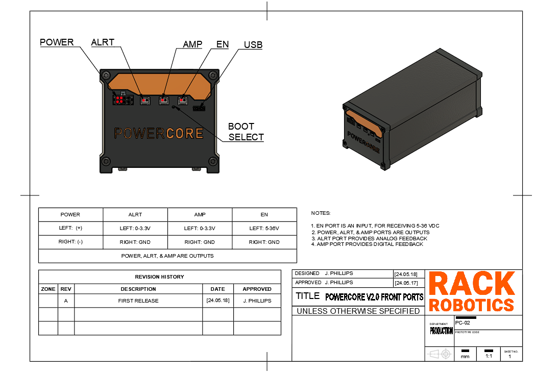
| POWER | The Powercore V2.0 outputs EDM waveforms through an 8-position Molex Micro-Fit 3.0 connector. The included output cable is 1 meter long and rated for 30 cycles. This cable consists of four twisted pairs to significantly reduce electromagnetic emissions. For more information about twisted wires and their benefits, refer to the best practices section. |
| ALRT | The Powercore V2.0 provides digital telemetry on the spark ignition rate via the ALRT port. The spark ignition rate, defined as the ratio of 'observed discharges' to 'possible discharges'. The spark ignition rate is a key indicator of feedrate efficiency. A low rate suggests the feedrate can be increased, while a high rate indicates an excessive feedrate or a short circuit. Telemetry is reported as a PWM duty cycle, which can be read by a control board or microcontroller. This port enables closed-loop feedrate control, ensuring optimal material removal. An ignition rate of approximately 80% has been observed to be optimal. |
| AMP | The Powercore V2.0 provides analog telemetry via the on-board current sensor (U17A, LMV358AIDGKR, output shunt). It is mapped to between 0V and 3.3V, at a rate of 12 mV/A. This may be used for closed-loop feedback control and debugging. |
| EN | The Powercore V2.0 features an "enable port" that ensures safety by requiring activation before the device outputs EDM waveforms. When the Powercore is plugged in, it remains inactive until the enable port receives a DC voltage between 5V and 36V. This port draws minimal current. The enable port can be connected to GPIO, motor, heater, or LED ports on a 3D printer or CNC control board, or controlled manually with a switch. To prevent damage, avoid disconnecting the main AC power while the enable port is active. |
| USB | A type-C USB port provides communication with the on-board RP2040 micronctroller and flash memory. Pressing the reset button (the pin-hole located between the ‘AMP’ and ‘EN’ ports) during power-up initiates the USB bootloader mode, allowing access to the flash memory. When the reset button is held down while powering up, the RP2040 enters a special state where it presents itself as a mass storage device to a connected computer. This enables users to drag and drop firmware files directly into the flash memory, facilitating easy updates and modifications without needing additional programming tools or interfaces. |
Best_Practices
⚠ Avoid touching the electrodes and workpiece during operation to prevent exposure to high-voltage DC (65V). Additionally, individuals with pacemakers or similar medical devices should not operate the Powercore, as the high-voltage environment could interfere with their functionality.
The Powercore V2.0 contains a custom SMPS and motherboard. The internal SMPS is rated for 300 W typical and 550 watts peak, and accepts a range of AC voltages and frequencies. The SMPS provides 72 VDC to the motherboard, via the motherboard input supply connector (J1). The motherboard converts the steady 72 VDC input power, into pulsed high-current DC power, which is suitable for EDM.
Theory of Operation
The Powercore V2.0 motherboard delivers parametric pulsed DC through the repeated charging and discharging of a 32.9 µF capacitor bank. Efficient and rapid capacitor charging is achieved via a peak current-mode control (PCMC) charger stage. The onboard RP2040 microcontroller monitors the capacitor voltage and adjusts the PCMC charger parameters accordingly. When an output pulse is needed, the RP2040 discharges the capacitor bank through the MOSFET-driven output stage into the POWER port. This design allows for precise control over the EDM output pulse parameters: on-time, off-time, and peak voltage.
⚠ Adjustment of the firmware, including the on-time, off-time, and peak-voltage, may lead to damage of the PCMC switching converter. Do so at your own risk.
Motherboard
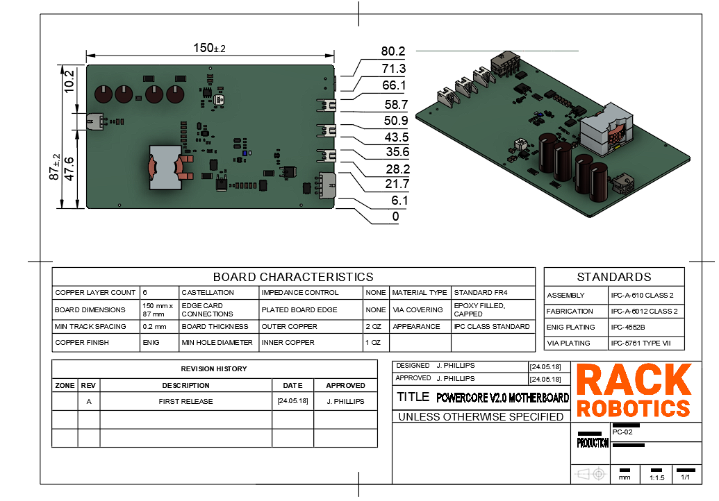
The motherboard contains multiple functional blocks:
Work in Progress
DANGER The Powercore V2.0 operates at a potentially hazardous voltage of 65 - 72 VDC, and supplies high-power waveforms
Improper use of the Powercore can increase radiated emission levels. These intrinsic properties of EDM necessitate operator care and supervision. Touching the workpiece or electrode(s) during EDM operation exposes the may expose the user to 65 - 72 VDC high-voltage. Individuals with pacemakers or similar medical devices should not operate the Powercore, as the high-voltage environment could interfere with their functionality. Ensure that proper measures are taken against EMI. Routing of EDM power through unshielded/twisted cables not recommended. Unshielded/twisted cables function as antennas, which will radiate emissions into the nearby
Shield: 
This work is licensed under a Creative Commons Attribution-NonCommercial 4.0 International License.

You are free to:
Under the following terms:
| Qty | Value | Footprint | References |
|---|---|---|---|
| 30 | 0.1U | Capacitor_SMD:C_0603_1608Metric | C1, C3, C4, C5, C15, C16, C22, C29, C35, C42, C44, C47, C48, C49, C56, C65 +14 |
| 22 | 10K0 | Resistor_SMD:R_0603_1608Metric | R1, R3, R7, R12, R16, R26, R38, R43, R46, R50, R56, R58, R75, R79, R80, R82 +6 |
| 15 | 4.7U | Capacitor_SMD:C_1206_3216Metric | C10, C11, C12, C13, C14, C17, C18, C19, C20, C21, C25, C34, C37, C53, C57 |
| 13 | 1U | Capacitor_SMD:C_0603_1608Metric | C23, C24, C26, C27, C30, C32, C52, C63, C64, C73, C76, C83, C86 |
| 13 | TestPoint | TestPoint:TestPoint_Pad_D1.5mm | TP1, TP2, TP3, TP4, TP5, TP6, TP7, TP8, TP9, TP10, TP13, TP15, TP16 |
| 12 | 1K00 | Resistor_SMD:R_0603_1608Metric | R4, R11, R15, R20, R30, R31, R39, R49, R72, R73, R100, R101 |
| 10 | 0.01U | Capacitor_SMD:C_0603_1608Metric | C6, C36, C38, C45, C59, C60, C72, C79, C81, C82 |
| 10 | 100R | Resistor_SMD:R_0603_1608Metric | R10, R18, R22, R33, R45, R47, R51, R65, R92, R96 |
| 9 | 100K | Resistor_SMD:R_0603_1608Metric | R14, R23, R27, R37, R40, R60, R61, R88, R89 |
| 6 | 47K0 | Resistor_SMD:R_0603_1608Metric | R5, R28, R41, R53, R63, R78 |
| 5 | 10R | Resistor_SMD:R_0603_1608Metric | R19, R21, R25, R62, R77 |
| 4 | 100U | THT_CAPACITORS:CP_Radial_D10.0mm_P5.00mm | C50, C51, C54, C55 |
| 4 | 27p | Capacitor_SMD:C_0603_1608Metric | C2, C40, C41, C46 |
| 4 | NetTie_2 | NET_TIES:NET_TIE_SMD_10mil | NT1, NT2, NT5, NT6 |
| 3 | 20K0 | Resistor_SMD:R_0603_1608Metric | R32, R64, R67 |
| 3 | DMG2302UK-7 | SOT:SOT-23-3 | Q2, Q7, Q11 |
| 3 | LMV358AIDGKR | Package_SO:VSSOP-8_3.0x3.0mm_P0.65mm | U6, U15, U17 |
| 3 | S2B-XH-A-1 | CONNECTORS:S2B-XH-A-1 | J3, J4, J5 |
| 3 | SS10PH10-M3/87A | Package_TO_SOT_SMD:TO-277A | D2, D6, D20 |
| 3 | V2PM10L-M3/H | DIODES:DO-220AA (SMP) | D1, D3, D4 |
| 2 | , | ||
| 2 | 0R006 | SMD_RESISTORS:CRE_2512_High_ohm | R24, R29 |
| 2 | 0R68 | SMD_RESISTORS:CSRN2512 | R13, R17 |
| 2 | 10K | Resistor_SMD:R_0603_1608Metric | R57, R59 |
| 2 | 2200p | Capacitor_SMD:C_0603_1608Metric | C31, C80 |
| 2 | 27R | Resistor_SMD:R_0603_1608Metric | R44, R66 |
| 2 | 2R7 | Resistor_SMD:R_1206_3216Metric | R54, R70 |
| 2 | 470p | Capacitor_SMD:C_0603_1608Metric | C84, C85 |
| 2 | 5K10 | Resistor_SMD:R_0603_1608Metric | R69, R71 |
| 2 | IRS10752LTRPBF | Package_TO_SOT_SMD:SOT-23-6 | U14, U16 |
| 2 | ISZ230N10NM6ATMA1 | DFN_QFN:INFINEON_TSDSON-8-25 | Q3, Q4 |
| 2 | LOGO | LOGO | G***, G*** |
| 2 | MSS1P3L-M3/89A | DIODES:D_MicroSMP_AK | D5, D19 |
| 2 | TK7R7P10PL,RQ | Package_TO_SOT_SMD:TO-252-2 | Q5, Q9 |
| 1 | 0430450400 | CONNECTORS:0430450400 | J1 |
| 1 | 0430450822 | CONNECTORS:0430450822 | J2 |
| 1 | 0R | Resistor_SMD:R_0603_1608Metric | R68 |
| 1 | 1000p | Capacitor_SMD:C_0603_1608Metric | C95 |
| 1 | 13K0 | Resistor_SMD:R_0603_1608Metric | R34 |
| 1 | 220p | Capacitor_SMD:C_0603_1608Metric | C39 |
| 1 | 22U | SMD_INDUCTORS:PQ2617BHA | L2 |
| 1 | 330U | SMD_INDUCTORS:VLS6045EX | L1 |
| 1 | 330n | Inductor_SMD:L_1210_3225Metric | L3 |
| 1 | 3R3 | Resistor_SMD:R_0603_1608Metric | R55 |
| 1 | 470K | Resistor_SMD:R_0603_1608Metric | R2 |
| 1 | 4K70 | Resistor_SMD:R_0603_1608Metric | R36 |
| 1 | 74LVC1G02SE-7 | Package_TO_SOT_SMD:SOT-353_SC-70-5 | U4 |
| 1 | ABLS-12.000MHZ-B2-T | CRYSTALS:Crystal_SMD_HC49-SD | Y1 |
| 1 | DMG2301L-7 | SOT:SOT-23-3 | Q1 |
| 1 | EVQ-P7A01P | SWITCHES:SW_SPST_EVQP7A | SW1 |
| 1 | GSB1C41110SSHR | CONNECTORS:GSB1C41110SSHR | J6 |
| 1 | INA281B2IDBVR | Package_TO_SOT_SMD:SOT-23-5 | U1 |
| 1 | LM5106MMX/NOPB | Package_SO:VSSOP-10_3x3mm_P0.5mm | U8 |
| 1 | LM5169FDDAR | TI_CONVERTERS:LM5169_POWERPAD_SOIC8 | U9 |
| 1 | MBT3946DW1T1G | Package_TO_SOT_SMD:SOT-363_SC-70-6 | Q12 |
| 1 | MMBD7000LT3G | Package_TO_SOT_SMD:SOT-23-3 | D7 |
| 1 | RP2040 | Package_DFN_QFN:QFN-56-1EP_7x7mm_P0.4mm_EP3.2x3.2mm | U2 |
| 1 | SN74LVC1G175DCKR | Package_TO_SOT_SMD:SOT-363_SC-70-6 | U3 |
| 1 | SN74LVC1G32DCKR | Package_TO_SOT_SMD:SOT-353_SC-70-5 | U5 |
| 1 | SSM6N815R,LF | TSOP_PACKAGES:TSOP_6_2.5MM WIDTH | Q10 |
| 1 | TLV3201AIDCKR | Package_TO_SOT_SMD:SOT-353_SC-70-5 | U13 |
| 1 | TLV7012DSGR | Package_SON:WSON-8-1EP_2x2mm_P0.5mm_EP0.9x1.6mm | U7 |
| 1 | UA78M05CDCYR | Package_TO_SOT_SMD:SOT-223-3_TabPin2 | U12 |
| 1 | UA78M33CKVURG3 | Package_TO_SOT_SMD:TO-252-2 | U10 |
| 1 | W25Q16JVSNIQ | Package_SO:SOIC-8_3.9x4.9mm_P1.27mm | U11 |
The 234 most common of 254 parts.
Shaxzodm2611/4-bit-Adder-Interface-Board
A custom PCB designed to mimic the function of a CPU. Entirely made from discrete logic ICs.

georges-mars/Docimeter
A wearable redesign of the OpenDosimeter platform focused on compact electronics, custom PCB integration, embedded firmware, and practical radiation-monitoring applications.


WheelchairSeniorDesign/PCBs
The PCB designs for the wheelchair for our senior design project

inspireFly-VT/ContentCube_Payload_Board
The payload board for inspireFly's ContentCube satellite.

HydrogreenPollub/legacy-pcb-energy-flow-unit
New Energy Flow pcb with step down CC CV converter


It measures 150 × 87 mm and has 6 copper layers, 1.64 mm thick.
254 parts, built around the RP2040, LMV358AIDGKRG, IRS10752LTRPBF and LM5106MMX/NOPB-JSM. The full list of its parts is on this page, with links to each part's symbol and footprint where PCBKit's library has them.
From the Rack-Robotics/Powercore-V2.0 repository on GitHub, at the commit this page was made from: the board is Powercore-V2.0 Motherboard/KiCAD/POWERCORE-V2.0_MOTHERBOARD.kicad_pcb and its schematic Powercore-V2.0 Motherboard/KiCAD/CHARGER_CONTROLS.kicad_sch. PCBKit opens the board in the browser, with nothing to install.
Its repository states no licence, so its author keeps all rights: ask Rack-Robotics before reusing the design.