2 layers144.1 × 108.1 mm

 ra0sms/nano-server
Server for hamradio remote operation
Nano server is an open-source printed circuit board by ra0sms, from the ra0sms/nano-server repository on GitHub, published under the MIT licence. It is a 2-layer board of 144.1 × 108.1 mm with 117 parts on 201 nets, routed with 1,627 tracks and 199 vias.
It is built around the K7805-500R3, MAX232N and PCF8574T, with the CM108B, SN74LVC2G14DBV and ULN2803A among its other parts. Its parts include 33 capacitors, 20 connectors, 17 resistors, 17 switches and 16 ICs. It belongs with the computers and single-board computers and radio and wireless boards of this library.


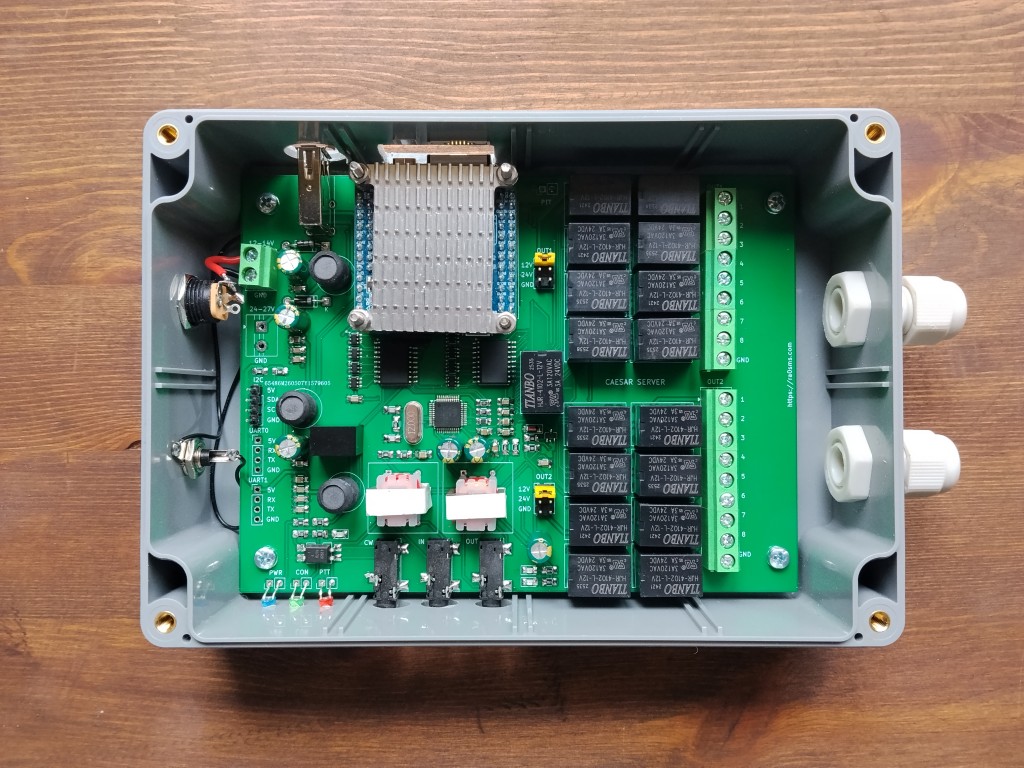
Nano Server is a server-side component of a remote ham radio station system. It runs on a NanoPi NEO single-board computer with Armbian and provides audio streaming, PTT control via GPIO, video streaming, relay switching, CAT interface forwarding, CW keying, and a web-based configuration interface.
Desktop client software: https://github.com/ra0sms/caesar-client-desktop
git pull + restart of all related systemd services) from the web UI| Component | Details |
|---|---|
| SBC | NanoPi NEO (Allwinner H3) |
| OS | Armbian (Debian Bookworm or later) |
| Audio | USB sound card (C-Media USB Audio Device) |
| Camera | USB webcam on /dev/video1 |
| Relay board | 2× I2C GPIO expander at 0x20 / 0x21 |
| CAT interface | USB-to-Serial (port chosen in web Settings tab, e.g. /dev/ttyUSB0) |
| CAT UART1 relay | Physical UART1 on /dev/ttyS1 (pins 8-TX, 10-RX) |
| CON LED | GPIO PC2 (line 66) |
| PTT output | GPIO PC3 (line 67) |
| CW Keyer output | GPIO PC1 (line 65) |
Client PC                          NanoPi NEO (Server)
─────────────────────────────────────────────────────────
                    UDP :5000  ←──  Audio TX (mic → client)
                    UDP :5000  ──→  Audio RX (client → speaker)
                    UDP :5001  ──→  PTT commands (0/1)
                    UDP :5002  ←→   Ping / RTT monitoring
                    UDP :5003  ──→  CW Keyer (Winkeyer protocol, UDP)
                    TCP :5050  ←──  Web UI (Flask): relays, TRX, band relay, audio, config, settings, update (live status over SSE)
                    TCP :6789  ←──  CW XML-RPC (PyWinKeyerSerial / not1mm)
                    TCP :3001  ←──  CAT (Icom CI-V or Kenwood)

Local PC (UART1)                   NanoPi NEO (Server)
─────────────────────────────────────────────────────────
UART1 (ttyS1) ←→ Transparent CAT relay (bidirectional)| Service | Description |
|---|---|
ptt_server | PTT + CW Keyer + client monitor + ping responder (single service, all GPIO) |
audio_server | GStreamer audio TX (server mic → client) |
audio_client_on_server | GStreamer audio RX (client → server speaker) |
relay-web | Web UI: relays, TRX, band relay, audio, config, settings, update (port 5050) |
mjpeg-streamer | MJPEG video stream from USB camera (localhost:8081 only; viewed through the web panel login) |
alsa_restore | Restores ALSA mixer state at boot |
git clone https://github.com/ra0sms/nano-server.git
cd /home/pi/nano-serversudo bash install_server.shThe script will:
client_ip.cfg, server_ip.cfg, and web/password.txt with defaults/boot/armbianEnv.txtrestart_services_on_server.sh, systemctl restart/stop/start relay-web, and alsactl store (so Audio tab volume changes persist across reboot)echo '192.168.1.100' > /home/pi/nano-server/client_ip.cfg # IP of the client PC
echo '192.168.1.10' > /home/pi/nano-server/server_ip.cfg # IP of this serverOr use the web interface at http://<server-ip>:5050/.
echo 'yourpassword' > /home/pi/nano-server/web/password.txtIf you have multiple USB audio devices (e.g., webcam with mic), the C-Media USB Audio card may not be card 0. Run:
sudo bash /home/pi/nano-server/fix_alsa_card_order.sh
sudo rebootsudo rebootThe script setup_armbian_env.sh patches /boot/armbianEnv.txt to enable the required device tree overlays. It never modifies rootdev or rootfstype so the system remains bootable.
To apply manually on a running system:
sudo bash /home/pi/nano-server/setup_armbian_env.sh
sudo reboot
Required overlays: i2c0 uart1 uart2 uart3 usbhost0 usbhost1 usbhost2 usbhost3 w1-gpio
Access at http://<ip>:5050/ (password protected).
Default password: 1234 — change it in web/password.txt.
| Tab | Description |
|---|---|
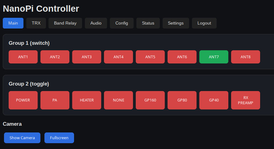
| Main | Relay switching (16 relays, toggle/switch modes) and camera view |
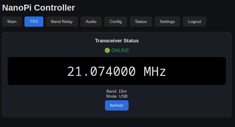
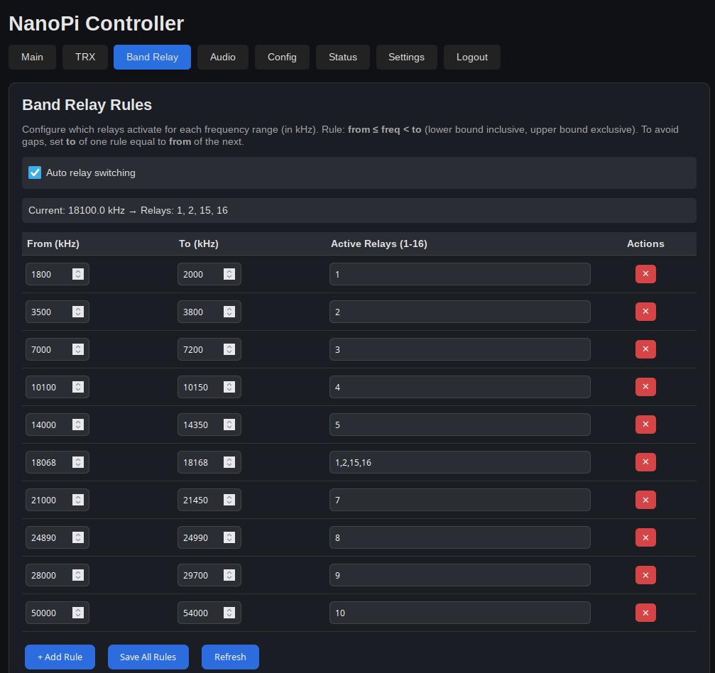
| TRX | Transceiver frequency, band, mode display, and Band Relay frequency-based automatic relay switching rules |
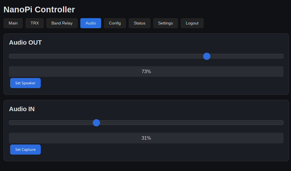
| Audio | Speaker and mic level control via ALSA, audio stream settings (sample rate/buffer), restart audio services |
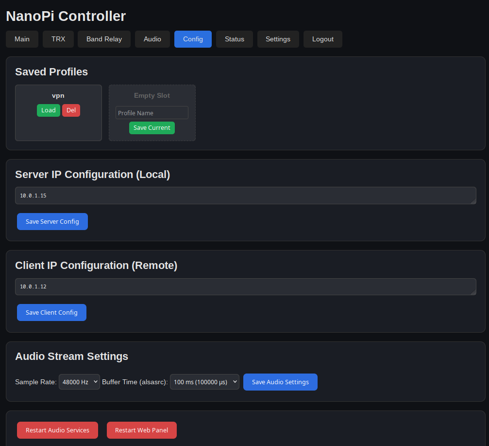
| Config | IP addresses, saved profiles, network status (client RTT / connection status, local IP) |
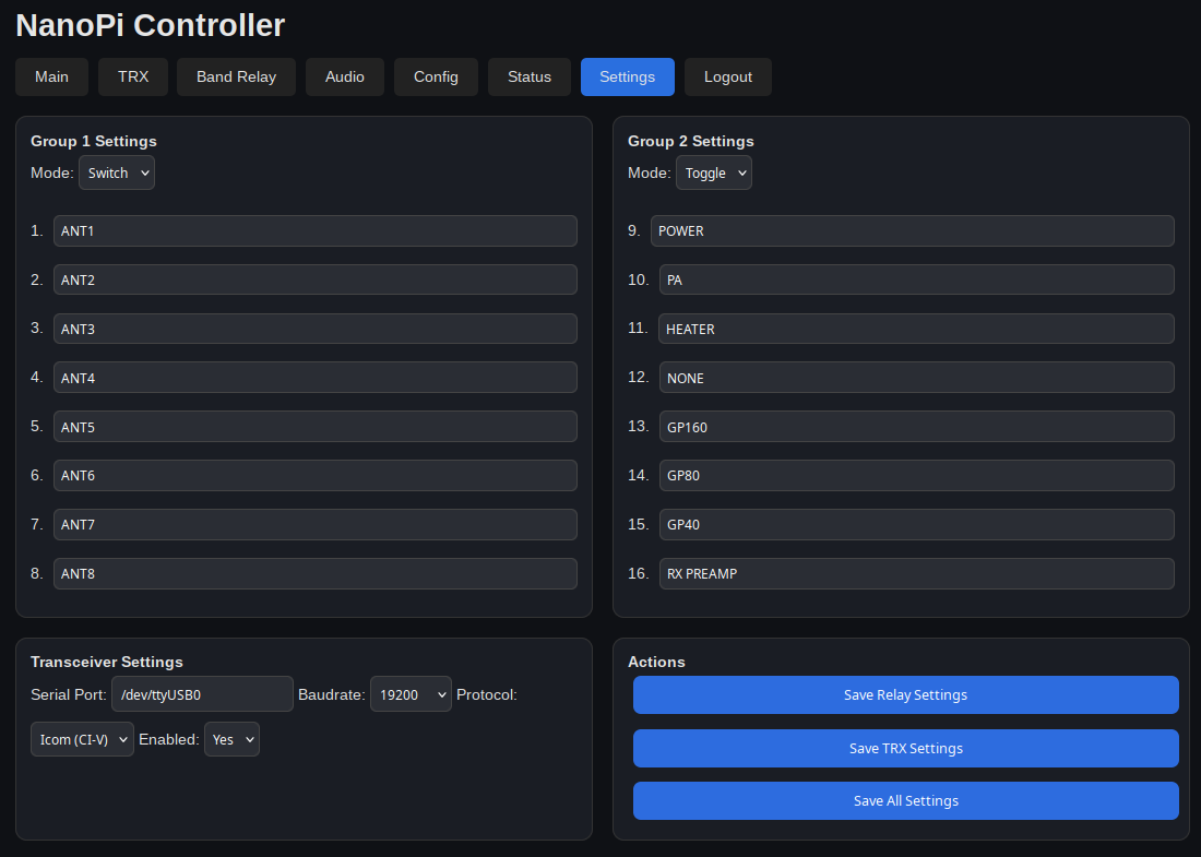
| Settings | Relay names, group modes, TRX serial port and protocol, UART1 transparent relay toggle |
| Update | Check GitHub for a newer release, view its changelog, apply the update and restart the web panel |
A status bar is shown at the top of every tab with the current PTT state, the transceiver online/frequency indicator, and the client link latency (RTT):
● PTT: ON) while transmitting, grey otherwise.🟢 ONLINE / 🔴 OFFLINE plus the live frequency.Live values are pushed to the browser over Server-Sent Events (SSE, GET /events). The server sends a combined snapshot (PTT, relay state, TRX frequency/band/mode, client RTT, band-relay current state) that is emitted only when it changes, replacing the previous per-tab HTTP polling every 2 s. This makes status changes appear immediately and reduces load on the device. The SSE stream requires an authenticated session (cookies are sent automatically by the browser) and reconnects automatically if dropped.
Configure which relays activate for each frequency range (in kHz). Rules use from ≤ freq < to logic (lower bound inclusive, upper bound exclusive). To avoid gaps, set to of one rule equal to from of the next.
Example:
1800-1840 kHz → relays 1, 21840-1900 kHz → relays 3, 47000-7300 kHz → relays 5, 6Auto-switching can be toggled on/off via a checkbox in the TRX tab. Rules are validated on the server (numeric from < to in kHz, relay numbers 1–16); if web/band_rules.json is unreadable at startup, it is renamed to band_rules.json.invalid and the default rules are used.
Group-scoped auto-switching: auto-switching only touches the relay group(s) that the configured rules actually reference, leaving the other group fully manual:
This makes it possible to dedicate one relay group to automatic antenna/band switching while keeping the other group for manually-controlled devices.
Switching only on a band change, with confirmation: relays are switched only when the frequency moves into a range with a different relay set, and only after two frequency readings at least 0.3 s apart agree. This means:
While a band change waits for its confirming reading, the server polls the transceiver right away (subject to the external-program collision guard), so the switch still happens promptly. Saving the rules or re-enabling auto-switching re-applies them on the next reading.
When PTT is active (transmitting), all relay switching is automatically blocked to prevent accidental antenna switching during transmission. This protects both the transceiver and the antenna system.
How it works:
combined_ptt_service.py broadcasts the GPIO PTT status via UDP on 127.0.0.1:5004 on every change and as a heartbeat every ~0.3 sweb/app.py listens for these broadcasts in a background thread. If no status has arrived for 1.5 s (the web panel just restarted, or ptt_server is stopped/crashed), the PTT state is treated as unknown and relays stay lockedTX…; / RX…;, Icom CI-V 1C 00 01 / 1C 00 00)IF reply and TX…;/RX…; auto-information, the Icom reply to 1C 00 (the server polls it on alternate poll cycles)not-allowed cursor). The status bar shows PTT: ON, PTT: ON (CAT), or an orange PTT: NO STATUS when ptt_server isn't reportingBlocked operations:
POST /toggle/<n> (server-side check)/trx/set_freq: band relays can't follow during TX, so a band change would leave the transmitter keyed into the previous band's antenna (the request is refused with HTTP 409 and a message in the UI). Frequency steps are also refused while the transceiver is offline, instead of stepping from a made-up frequencyThe server can transparently relay all CAT data between the transceiver (connected via the USB-to-Serial CAT port selected in web Settings) and a local computer connected to the UART1 physical port (/dev/ttyS1, pins 8-TX, 10-RX on NanoPi NEO). This allows two clients to share the same CAT connection simultaneously:
127.0.0.1, the client IP from client_ip.cfg, and the IPs listed in tcp_allowed_ips in web/trx_config.json (edit the file, then restart relay-web; e.g. "tcp_allowed_ips": ["192.168.1.50"]) may connect; other connections are closed immediately, since this port can key and retune the transmitterHow it works:
Configuration (in web/trx_config.json or via web UI Settings tab):
{
    "uart1_enabled": true,
    "uart1_port": "/dev/ttyS1"
}
The UART1 baudrate is automatically set to match the CAT port baudrate.
Replies to the server's own requests are not forwarded. The server's own polls (and the web UI's TRX commands) would otherwise produce replies that external programs take as answers to their own requests, causing "unexpected reply" errors and retries in Hamlib/JTDX/flrig:
server_addr, default 0xE1), not the 0xE0 that flrig/JTDX/Hamlib use (ctrl_addr). The radio replies to the sender's address, so frames to or from server_addr (including the echo on a single-wire CI-V bus) are decoded for the web UI but not passed to TCP clients or UART1. If some radio only works with 0xE0, set Server CI-V Address to 0xE0: everything is then forwarded, as in older versions.IF; poll the next IF…; reply (within 0.5 s) is kept back from external programs. If UART1 is unavailable (e.g., overlay not enabled), the server logs a warning and continues without it.Web UI toggle: The Settings → Transceiver Settings tab now includes a "UART1 transparent relay" checkbox. It can be turned on/off directly from the web interface and takes effect immediately (the relay is re-initialized without restarting the service).
Poller behavior with the relay enabled:
When the UART1 transparent relay is enabled, the CAT bus can be owned by an external program on the PC (e.g. flrig, TR4W, Hamlib). While the external program is actively exchanging data, the server's internal poller backs off so its queries do not interleave with the PC's requests on the same line and corrupt the response stream.
However, the server now automatically resumes its own polling whenever the external program is silent or absent:
This behavior applies to both CAT protocols (Icom CI-V and Kenwood).
"Recently" means the radio has reported the active frequency in the last 2 s; other CAT traffic doesn't count (e.g. Hamlib reading only the inactive VFO).
What the web panel decodes:
03/04) and the radio's own transceive reports (00/01). With CI-V Transceive enabled in the radio's menu, frequency changes arrive as soon as the dial moves, so band relays react without waiting for a poll. Modes: LSB, USB, AM, CW, CW-R, RTTY, RTTY-R, FM, WFM, DV, DD. 6-byte frequencies (10 GHz+ bands, IC-905) are supported.IF (frequency, mode, TX/RX and active VFO), FA/FB, MD, FR. FA/FB only update the displayed frequency and band relays when they are for the VFO the radio is operating on (learned from IF, FR reports and FR commands external programs send). Otherwise, working on VFO B would switch antennas by VFO A's frequency. Frequency changes from the web UI are sent to the active VFO (FB when on VFO B).Stability & auto-recovery:
All writes to the CAT port are serialized through a single thread lock (ser_lock), and data from each external source (every TCP client and UART1) is first split into whole CAT frames (terminated by ; for Kenwood, 0xFD for CI-V) — only complete frames are written. So a command that arrives in pieces (e.g. F in one TCP segment and A; in the next) can never have the poller's or another client's frame inserted into its middle. An unterminated tail is passed through as-is after 0.5 s. The CAT port and UART1 are read without a fixed 100 ms wait, so replies reach JTDX/flrig and UART1 immediately. Additionally, if the CAT serial port raises a read error (e.g. a temporary USB hiccup or the transceiver is powered off), the server now automatically closes and reopens the serial ports with retries instead of silently stalling — so a remote JTDX, flrig, or WSJT-X session no longer needs a full service restart to recover. Manually re-initializing from the web UI (Reconnect button / POST /trx/reinit) and re-initializing after a config change are also guarded by the same lock.
Prerequisite: UART1 overlay must be enabled in /boot/armbianEnv.txt:
overlays=i2c0 uart1 uart2 uart3 usbhost0 usbhost1 usbhost2 usbhost3 w1-gpioUp to 5 configuration profiles (server IP, client IP, audio settings) can be saved and loaded from the web configuration interface. Profile files are stored in profiles/.
To restart all runtime services at once:
sudo /home/pi/nano-server/restart_services_on_server.shOr restart individual services:
sudo systemctl restart ptt_server.service
sudo systemctl restart audio_server.service
To restart the web panel from the UI, use the "Restart Web Panel" button on the Update tab (requires sudoers NOPASSWD for systemctl restart relay-web). The "Restart Audio Services" button on the Audio tab restarts audio_server, audio_client_on_server, mjpeg-streamer, and ptt_server (via restart_services_on_server.sh).
To reload client_ip.cfg without restarting the PTT service:
sudo systemctl kill -s SIGHUP ptt_server.serviceThe Update tab checks GitHub for a newer release and applies it without needing SSH access to the server.
origin and compares the highest vX.Y.Z tag to the version reachable from the currently checked-out commit (git describe --tags). If a newer one exists, it shows every CHANGELOG.txt section newer than the current version (not just the latest one), read directly from the fetched tag so it's visible even before pulling.git pull --ff-only, then restarts audio_server, audio_client_on_server, mjpeg-streamer, and ptt_server (via restart_services_on_server.sh), and finally restarts relay-web itself.web/config.json, audio/audio_config.cfg, web/trx_config.json, web/band_rules.json — these are gitignored and rewritten by the app itself, so their local content is preserved across the pull automatically). A stray file left in the checkout (e.g. a manual backup) will block the update until it's removed or committed elsewhere.Cutting a new release: add a ## vX.Y.Z (date) section with a bullet list to the top of CHANGELOG.txt, commit, then tag and push:
git tag vX.Y.Z
git push origin main
git push origin vX.Y.ZEdit audio/audio_config.cfg:
RATE=48000       # sample rate: 48000 or 24000 Hz
LATENCY=100000   # buffer time in microseconds (100 ms)
Or use the Audio Stream Settings section on the Audio page in the web UI.
The web panel auto-detects the ALSA card (looks for C-Media USB Audio in /proc/asound/cards) and the speaker control name. Mic capture is hardcoded to numid=8 (Mic Capture Volume).
The CW Keyer is integrated into the ptt_server service (single process, single GPIO request). It implements the K1EL Winkeyer protocol over UDP, generating Morse code (CW) on GPIO PC1 (line 65).
All GPIO lines (CW=PC1, CON=PC2, PTT=PC3) are requested in a single gpiod.request_lines() call to avoid conflicts between separate processes on the same gpiochip.
| Byte | Command | Description |
|---|---|---|
0x00 + WPM | Set speed | WPM value (5-99) |
0x02 | Start sending | Begin transmitting buffer |
0x03 | Clear buffer | Reset and stop |
0x0A (LF) | Start sending | Same as 0x02 |
0x1B | Immediate stop | Abort transmission |
0x1F | Request status | Reply: 0x00 (idle) or 0x01 (busy) |
0x20-0x7E | ASCII chars | Add to send buffer |
0x7F | Backspace | Remove last char from buffer |
# Send "CQ CQ DE RA0SMS" at 25 WPM
echo -ne '\x00\x19CQ CQ DE RA0SMS\x0a' | nc -u <server-ip> 5003The service provides an XML-RPC server on TCP port 6789, compatible with the K6GTE PyWinKeyerSerial interface. This allows logging programs like not1mm to send CW directly to the server.
Port 6789 is the CW connection used by not1mm. In not1mm's CW settings this corresponds to cwport = 6789 with cwtype = 2 (PyWinKeyerSerial). The corresponding not1mm UI fields are:
PyWinKeyerSerial<server-ip>6789⚠️ Important — re-check not1mm.json manually after any IP change. not1mm stores its CW server address in the
cwipfield of its settings file~/.config/not1mm/not1mm.json. If the IP address of this Nano Server changes, you must editcwipin that file (and ideally restart not1mm), because not1mm will not start / will fail to work if the configuredcwipis unreachable. Thecwport(must be6789) andcwtype(must be2) are stored there as well.
Example ~/.config/not1mm/not1mm.json (relevant CW fields):
{
    "cwip": "10.0.1.16",
    "cwport": 6789,
    "cwtype": 2,
    "useflrig": true,
    "cw_speed": 30
}
Available RPC methods:
| Method | Description |
|---|---|
k1elsendstring(text) | Send a string to the CW buffer and start transmitting |
setspeed(wpm) | Set CW speed (5-99 WPM) |
sendblended(text) | Send a prosign/blended message |
tuneon() | Key down and hold (tune mode) |
tuneoff() | Stop key down |
clearbuffer() | Clear the CW buffer and stop sending |
Example using Python:
import xmlrpc.client
proxy = xmlrpc.client.ServerProxy("http://<server-ip>:6789/RPC2")
proxy.k1elsendstring("CQ CQ DE RA0SMS")
proxy.setspeed(25)sudo systemctl status ptt_server.service
sudo systemctl restart ptt_server.service
sudo journalctl -u ptt_server.service -fnano-server/
├── install_server.sh # Main installation script
├── setup_armbian_env.sh # Patches /boot/armbianEnv.txt safely
├── restart_services_on_server.sh # Restart all runtime services
├── fix_alsa_card_order.sh # Fix USB audio card order via modprobe
├── setup_sudo_nopasswd.sh # Configure sudoers for web panel self-restart
├── create_ser2net_yaml.sh # Generate ser2net config
├── client_ip.cfg # Client IP (git-ignored)
├── server_ip.cfg # Server IP (git-ignored)
├── CHANGELOG.txt # Per-version release notes, read by the Update tab
├── armbianEnv.txt # Reference overlay config
├── audio/
│ ├── audio_server.sh # GStreamer TX pipeline
│ ├── audio_client_on_server.sh # GStreamer RX pipeline
│ └── audio_config.cfg # Rate and buffer settings (git-ignored, written by the app)
├── network/
│ └── combined_ptt_service.py # PTT + CW Keyer + client monitor + ping responder
├── web/
│ ├── app.py # Web UI: relays, TRX, band relay, audio, config, settings, update (+ live status via SSE /events)
│ ├── templates/index.html # Web UI page markup (rendered via render_template)
│ ├── static/css/style.css # Web UI stylesheet
│ ├── static/js/main.js # Web UI client-side logic
│ ├── config.json # Relay names and group modes (git-ignored, written by the app)
│ ├── trx_config.json # TRX serial port and protocol settings (git-ignored, written by the app)| Qty | Value | Footprint | References |
|---|---|---|---|
| 18 | 100n | Capacitor_SMD:C_1206_3216Metric | C2, C5, C10, C11, C12, C13, C14, C15, C16, C17, C22, C23, C30, C31, C32, C33 +2 |
| 17 | TIANBO-HJR-4102-L | Relay_THT:Relay_SPDT_CUI_SR5 | K1, K2, K3, K4, K5, K6, K7, K8, K10, K18, K19, K20, K21, K22, K23, K24 +1 |
| 8 | SN74LVC2G14DBV | Package_TO_SOT_SMD:SOT-23-6 | U3, U4, U5, U6, U10, U11, U12, U13 |
| 7 | 10u | Capacitor_SMD:C_1206_3216Metric_Pad1.33x1.80mm_HandSolder | C4, C9, C20, C21, C24, C25, C26 |
| 6 | 1k | Resistor_SMD:R_1206_3216Metric | R1, R2, R3, R4, R10, R32 |
| 4 | 47uF | Capacitor_THT:CP_Radial_D5.0mm_P2.50mm | C1, C3, C7, C29 |
| 4 | MountHole | MountingHole:MountingHole_3.2mm_M3_DIN965_Pad | J13, J14, J15, J16 |
| 2 | 10 | Resistor_SMD:R_1206_3216Metric | R12, R13 |
| 2 | 1N4007 | Diode_THT:D_DO-41_SOD81_P10.16mm_Horizontal | D1, D8 |
| 2 | 22 | Capacitor_SMD:C_1206_3216Metric_Pad1.33x1.80mm_HandSolder | C18, C19 |
| 2 | 22 | Resistor_SMD:R_1206_3216Metric | R7, R8 |
| 2 | 3k | Resistor_SMD:R_1206_3216Metric | R14, R15 |
| 2 | 470 | Resistor_SMD:R_1206_3216Metric | R6, R9 |
| 2 | 470uF | Capacitor_THT:CP_Radial_D5.0mm_P2.50mm | C27, C28 |
| 2 | 600:600 | Transformer_THT:Transformer_NF_ETAL_1-1_P1200 | T1, T2 |
| 2 | PCF8574T | Package_SO:SOIC-16W_7.5x10.3mm_P1.27mm | U2, U9 |
| 2 | ULN2803A | Package_SO:SOIC-18W_7.5x11.6mm_P1.27mm | U7, U14 |
| 1 | 10k | Resistor_SMD:R_1206_3216Metric | R11 |
| 1 | 10uH | Resistor_SMD:R_1206_3216Metric | L4 |
| 1 | 12-14V | TerminalBlock:TerminalBlock_MaiXu_MX126-5.0-02P_1x02_P5.00mm | J1 |
| 1 | 12MHz | Crystal:Crystal_HC18-U_Vertical | Y1 |
| 1 | 1M | Resistor_SMD:R_1206_3216Metric | R5 |
| 1 | 220 | Capacitor_SMD:C_1206_3216Metric | R33 |
| 1 | 24-27V | TerminalBlock:TerminalBlock_MaiXu_MX126-5.0-02P_1x02_P5.00mm | J10 |
| 1 | BC817 | Package_TO_SOT_SMD:SOT-23 | Q1 |
| 1 | CM108B | Package_QFP:LQFP-48_7x7mm_P0.5mm | U8 |
| 1 | CW | Connector_Audio:Jack_3.5mm_CUI_SJ-3523-SMT_Horizontal | J18 |
| 1 | FROM_TRX | Connector_Audio:Jack_3.5mm_CUI_SJ-3523-SMT_Horizontal | J9 |
| 1 | I2C | Connector_PinHeader_2.54mm:PinHeader_1x04_P2.54mm_Vertical | J17 |
| 1 | IN | LED_SMD:LED_1206_3216Metric | D7 |
| 1 | K7805-500R3 | Package_TO_SOT_THT:TO-220-3_Vertical | U1 |
| 1 | LED_CON | Connector_PinHeader_2.54mm:PinHeader_1x02_P2.54mm_Vertical | D2 |
| 1 | LED_CW | LED_SMD:LED_1206_3216Metric | D25 |
| 1 | LED_PTT | Connector_PinHeader_2.54mm:PinHeader_1x02_P2.54mm_Vertical | D4 |
| 1 | LED_PWR | Connector_PinHeader_2.54mm:PinHeader_1x02_P2.54mm_Vertical | D3 |
| 1 | LL4148 | Diode_SMD:D_MiniMELF | D5 |
| 1 | LTV-817S | Package_DIP:SMDIP-4_W9.53mm | U15 |
| 1 | Left_Side | Connector_PinSocket_2.54mm:PinSocket_2x12_P2.54mm_Vertical | J2 |
| 1 | MAX232 | Package_SO:SOIC-16_3.9x9.9mm_P1.27mm | U16 |
| 1 | OUT | LED_SMD:LED_1206_3216Metric | D6 |
| 1 | OUT_1 | TerminalBlock:TerminalBlock_MaiXu_MX126-5.0-09P_1x09_P5.00mm | J7 |
| 1 | OUT_2 | TerminalBlock:TerminalBlock_MaiXu_MX126-5.0-09P_1x09_P5.00mm | J12 |
| 1 | PTT_OUT | Connector_PinHeader_2.54mm:PinHeader_1x02_P2.54mm_Vertical | J5 |
| 1 | RS232 | Connector_PinHeader_2.54mm:PinHeader_1x04_P2.54mm_Vertical | J20 |
| 1 | Right_Side | Connector_PinSocket_2.54mm:PinSocket_2x12_P2.54mm_Vertical | J3 |
| 1 | SELECT_OUT_1 | Connector_PinHeader_2.54mm:PinHeader_2x03_P2.54mm_Vertical | J11 |
| 1 | SELECT_OUT_2 | Connector_PinHeader_2.54mm:PinHeader_2x03_P2.54mm_Vertical | J6 |
| 1 | TO_TRX | Connector_Audio:Jack_3.5mm_CUI_SJ-3523-SMT_Horizontal | J8 |
| 1 | UART0 | Connector_PinHeader_2.54mm:PinHeader_1x04_P2.54mm_Vertical | J19 |
| 1 | USB_A | Connector_USB:USB_A_Wuerth_614004134726_Horizontal | J4 |
It measures 144.1 × 108.1 mm and has 2 copper layers, 1.6 mm thick.
117 parts, built around the K7805-500R3, MAX232N, PCF8574T and CM108B. The full list of its parts is on this page, with links to each part's symbol and footprint where PCBKit's library has them.
From the ra0sms/nano-server repository on GitHub, at the commit this page was made from: the board is KiCad/nano-server/nano-server.kicad_pcb and its schematic KiCad/nano-server/nano-server.kicad_sch. PCBKit opens the board in the browser, with nothing to install.
Its repository publishes it under the MIT licence: you may reuse it on that licence's terms (keep the author's notice, and for a copyleft licence share your changes alike).

kwiecinski/BMS-and-offgrid-photovoltaic-management-system
Project contains BMS for lead-acid batteries and ESP-based board used to pull information from EASUN offgrid inverter, energy meters and sensors.


KozaMateusz/TemperatureManagementGUI
Graphical user interface to controll the temperature in a chamber.

galopago/misistemita
Electronic hardware prototyping system. Solderless, robust and open source. Solves the typical problem of the circuit that works on a breadboard but stops working on a real-world setup.


WestianPKl/Logger_Dashboard
A full-stack IoT monitoring platform for collecting, visualizing, and managing environmental sensor data from distributed devices.
