2 layers50.1 × 16.8 mm
PS-5V1.4A-7W EE13-Demo board
TDLOGY/HW_AC-DC-Flyback-5W-5V1A-Reference-Design
AC DC Flyback 5W 5V1A Reference Design
24 parts4

 ra0sms/ethernet-control-console1
Ethernet control console
Lan outlet is an open-source printed circuit board by ra0sms, from the ra0sms/ethernet-control-console repository on GitHub, published under the MIT licence. It is a 2-layer board of 88 × 78 mm with 58 parts on 84 nets, routed with 421 tracks and 30 vias.
It is built around the LM2575-3.3WU, UDN2981A-T and ULN2803A, with the SR240 among its other parts. Its parts include 16 fuses, 11 diodes, 10 resistors, 6 capacitors and 3 ICs. It belongs with the interfaces and adapters and radio and wireless boards and the STM32 boards of this library.


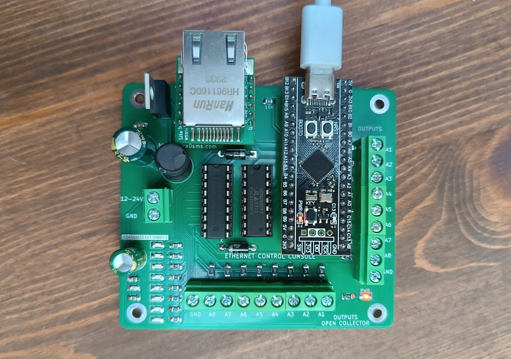
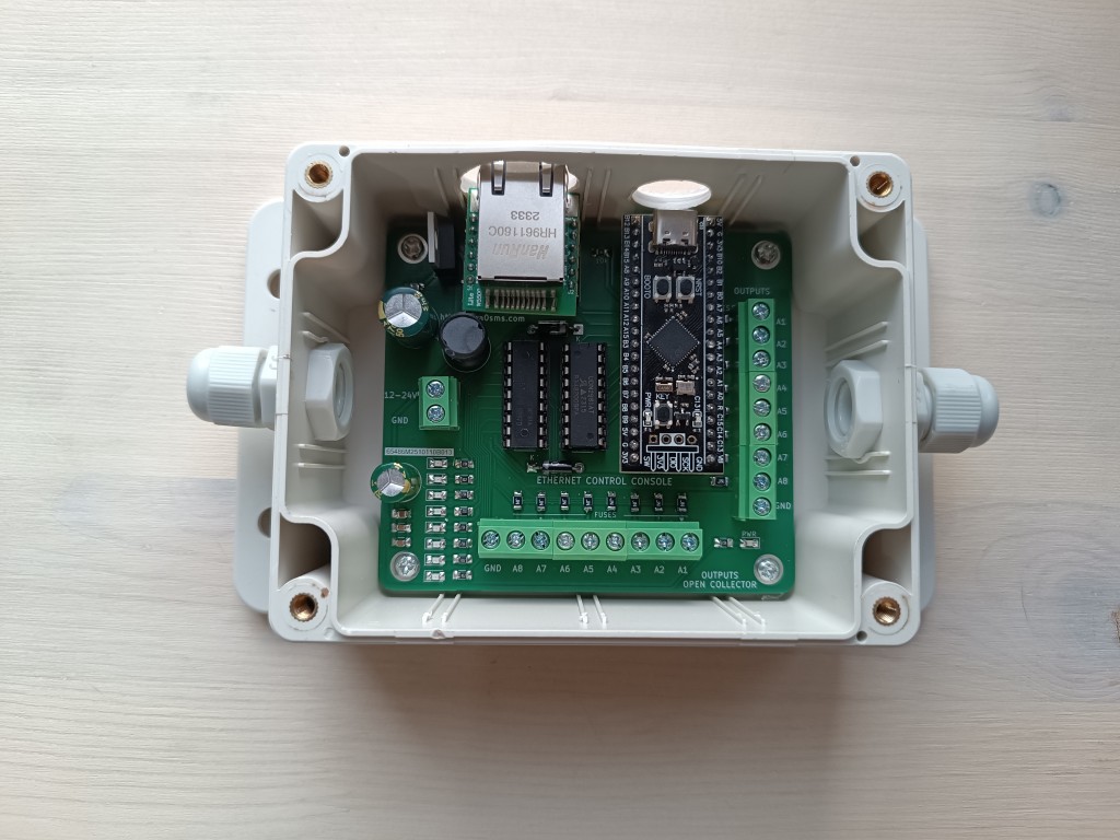
A device for controlling 8 outputs over Ethernet using a built-in web interface. The main outputs switch voltage, and each one is duplicated by an open-collector output.
It is built on an STM32F401 (Black Pill) and a W5500 Ethernet controller. You can configure it over USB with a console or the GUI application.
| Parameter | Value |
|---|---|
| Input voltage | 5–45 V DC |
| Output current | 500 mA total for all 8 outputs (and 500 mA total for open-collector outputs) |
| Interface | Ethernet 10/100 (W5500), USB (virtual COM port) |
| MCU | STM32F401CCU6 / STM32F401CEU6 (Black Pill) |
| PCB size | 78 × 88 mm |
You select the mode in the web interface. It is saved together with the other settings.
| Mode | Behavior |
|---|---|
| Toggle | Each output toggles independently |
| Switch | Only one output is on at a time; turning one on turns the others off |
| Dual | Outputs 1–4 and 5–8 form two groups, each with its own Toggle/Switch mode |
Prebuilt firmware is in firmware/:
w5500_outlet.hex – contains its own addressesw5500_outlet.bin – write to address 0x08000000STM32CubeProgrammer:
STM32_Programmer_CLI -c port=SWD -w firmware/w5500_outlet.hex -v -rstst-flash:
st-flash --reset write firmware/w5500_outlet.bin 0x08000000-c port=USB1) or dfu-util:dfu-util -a 0 -s 0x08000000:leave -D firmware/w5500_outlet.binSettings are stored in flash sector 5 (
0x08020000–0x0803FFFF), separately from the firmware. A normal firmware update keeps the settings. A full chip erase resets them to defaults.
| Parameter | Value |
|---|---|
| IP | 192.168.0.250 |
| Subnet mask | 255.255.255.0 |
| Gateway | 192.168.0.1 |
| DNS | 8.8.8.8 |
| MAC | 00:08:DC:AB:CD:EF |
| Web login / password | admin / password |
If you use more than one device on the same network, give each one its own IP and MAC address.
Open http://<device IP>/ in a browser and log in (HTTP Basic Auth).
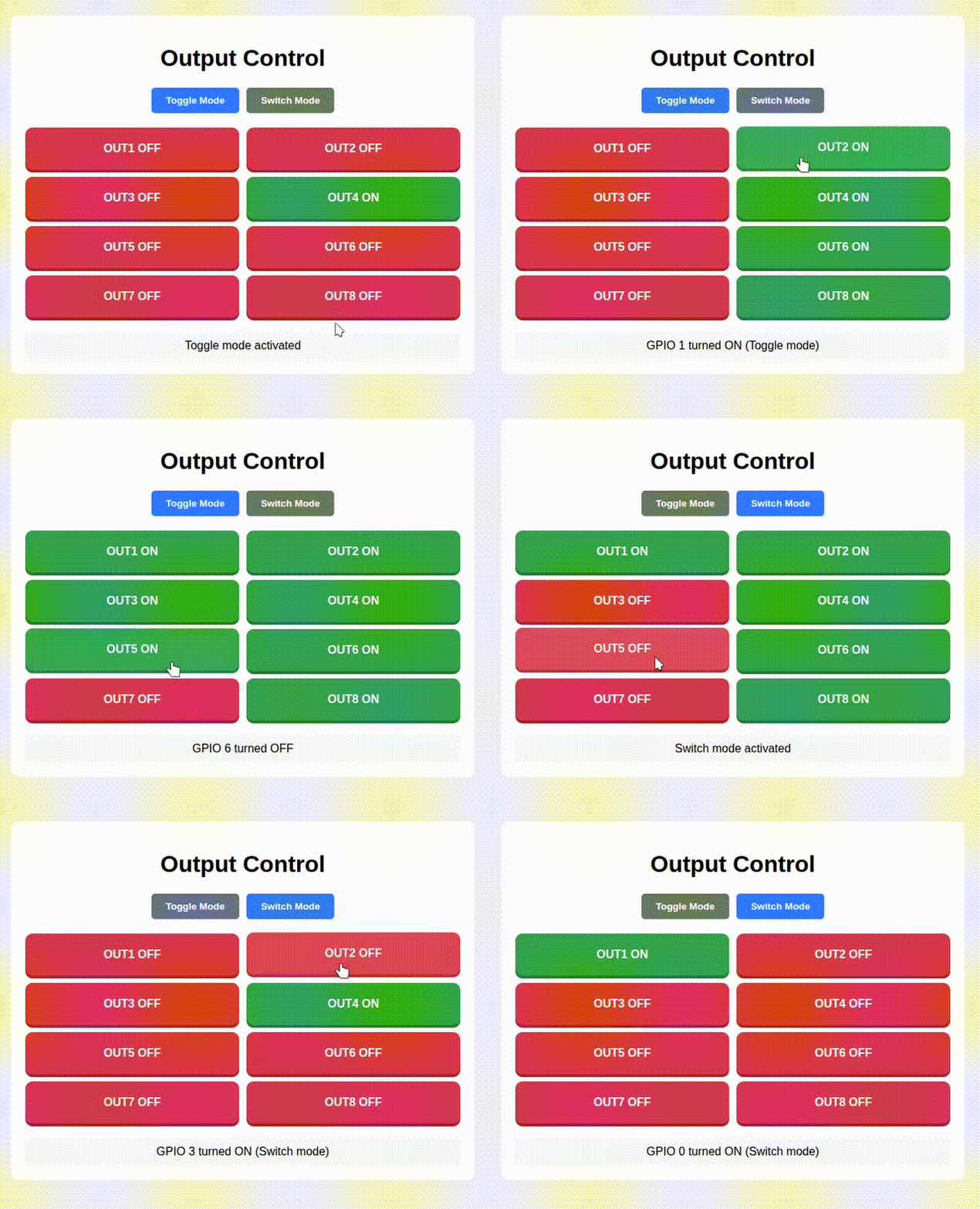
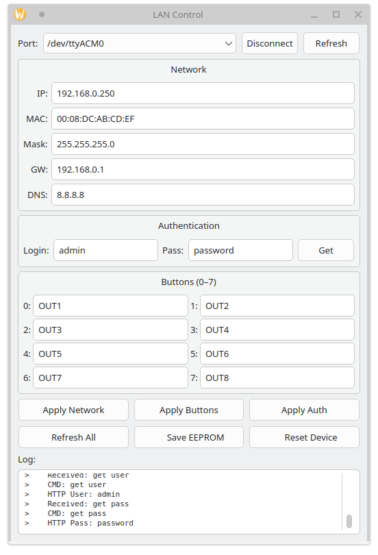
When you connect the board over USB, it appears as a virtual COM port (STM32 Virtual ComPort). Any port speed works.
You can configure it without the W5500 or the rest of the circuit: a bare Black Pill on USB is enough. The firmware detects the W5500 automatically and starts the web server when the module is connected.
gui/ contains a GUI application: gui.py (Python 3, pyserial, PyQt5) and a Windows build in gui-lan.zip.
| Command | Description |
|---|---|
help | List commands |
network | Show network settings |
set ip <x.x.x.x> | Set IP address |
set subnet <x.x.x.x> | Set subnet mask (alias: sn) |
set gateway <x.x.x.x> | Set gateway (alias: gw) |
set dns <x.x.x.x> | Set DNS server |
set mac <xx:xx:xx:xx:xx:xx> | Set MAC address |
set user <name> | Set web login (1–31 characters) |
set pass <password> | Set web password (up to 31 characters) |
get <ip|mac|subnet|gateway|dns|user|pass> | Show a parameter |
buttons | Show output names |
setbutton <0-7> <name> | Rename an output (up to 15 characters) |
save | Save settings to flash |
load | Load settings from flash |
default | Reset to factory defaults and save |
reset | Reboot the device |
Changes take effect immediately, but they are saved only after save.
Example:
set ip 192.168.1.50
set gateway 192.168.1.1
setbutton 0 Antenna1
save
reset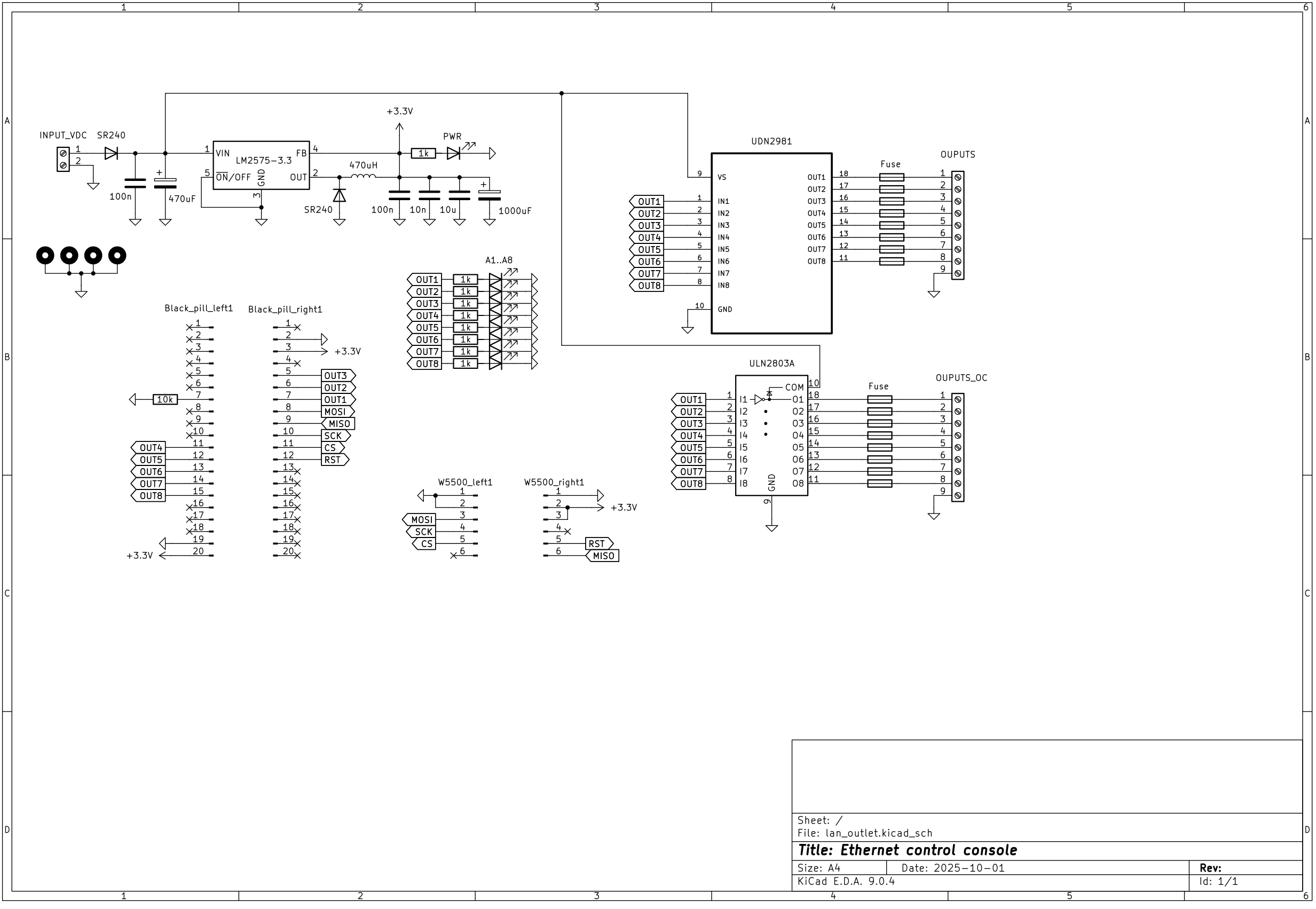
| Function | STM32 pins |
|---|---|
| Outputs 1–8 | PB0–PB7 |
| W5500 SPI (SCK / MISO / MOSI) | PA5 / PA6 / PA7 |
| W5500 CS | PA4 |
| W5500 RST | PA3 |
| Status LED | PC13 |
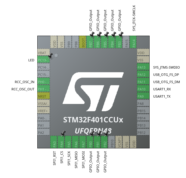
The project is in code/ and is built with STM32CubeIDE (open code/ as an existing project). PCB files are in KiCad/.
To build from the command line, use the toolchain bundled with STM32CubeIDE (the generic arm-none-eabi-gcc does not support the -fcyclomatic-complexity flag):
export PATH=/opt/st/stm32cubeide_<version>/plugins/com.st.stm32cube.ide.mcu.externaltools.gnu-tools-for-stm32.<version>/tools/bin:$PATH
cd code/Debug && make -j8 allSee LICENSE.
| Qty | Value | Footprint | References |
|---|---|---|---|
| 16 | Fuse | Resistor_SMD:R_1206_3216Metric | F1, F2, F3, F4, F5, F6, F7, F8, F9, F10, F11, F12, F13, F14, F15, F16 |
| 9 | 1k | Resistor_SMD:R_1206_3216Metric | R2, R3, R4, R5, R6, R7, R8, R9, R10 |
| 8 | A1 | Diode_SMD:D_1206_3216Metric | D4, D5, D6, D7, D8, D9, D10, D11 |
| 4 | MountingHole_Pad | MountingHole:MountingHole_3.2mm_M3_Pad | H1, H2, H3, H4 |
| 2 | 100n | Capacitor_SMD:C_1206_3216Metric | C1, C3 |
| 2 | Conn_01x06_Pin | Connector_PinHeader_2.54mm:PinHeader_1x06_P2.54mm_Vertical | W5500_left1, W5500_right1 |
| 2 | Conn_01x20_Pin | Connector_PinHeader_2.54mm:PinHeader_1x20_P2.54mm_Vertical | Black_pill_left1, Black_pill_right1 |
| 2 | SR240 | Diode_THT:D_DO-41_SOD81_P10.16mm_Horizontal | D1, D2 |
| 1 | 1000uF | Capacitor_THT:CP_Radial_D8.0mm_P3.80mm | C6 |
| 1 | 10k | Resistor_SMD:R_1206_3216Metric | R1 |
| 1 | 10n | Capacitor_SMD:C_1206_3216Metric | C4 |
| 1 | 10u | Capacitor_SMD:C_1206_3216Metric | C5 |
| 1 | 470uF | Capacitor_THT:CP_Radial_D10.0mm_P5.00mm | C2 |
| 1 | 470uH | Inductor_THT:L_Radial_D10.0mm_P5.00mm_Neosid_SD12_style3 | L1 |
| 1 | INPUT_VDC | TerminalBlock_MetzConnect:TerminalBlock_MetzConnect_Type055_RT01502HDWU_1x02_P5.00mm_Horizontal | J1 |
| 1 | LM2575-3.3 | Package_TO_SOT_THT:TO-220-5_Vertical | U1 |
| 1 | OUPUTS | TerminalBlock:TerminalBlock_MaiXu_MX126-5.0-09P_1x09_P5.00mm | J2 |
| 1 | OUPUTS_OC | TerminalBlock:TerminalBlock_MaiXu_MX126-5.0-09P_1x09_P5.00mm | J3 |
| 1 | PWR | Diode_SMD:D_1206_3216Metric | D3 |
| 1 | UDN2981 | Package_DIP:DIP-18_W7.62mm_LongPads | U2 |
| 1 | ULN2803A | Package_DIP:DIP-18_W7.62mm_LongPads | U3 |
It measures 88 × 78 mm and has 2 copper layers, 1.6 mm thick.
58 parts, built around the LM2575-3.3WU, UDN2981A-T, ULN2803A and SR240. The full list of its parts is on this page, with links to each part's symbol and footprint where PCBKit's library has them.
From the ra0sms/ethernet-control-console repository on GitHub, at the commit this page was made from: the board is KiCad/lan_outlet/lan_outlet.kicad_pcb and its schematic KiCad/lan_outlet/lan_outlet.kicad_sch. PCBKit opens the board in the browser, with nothing to install.
Its repository publishes it under the MIT licence: you may reuse it on that licence's terms (keep the author's notice, and for a copyleft licence share your changes alike).
TDLOGY/HW_AC-DC-Flyback-5W-5V1A-Reference-Design
AC DC Flyback 5W 5V1A Reference Design

cva68/ESPBreadboardRobot
Peripheral and breakout board for the ESP-32, with firmware designed for use with Microsoft MakeCode

TheBroKendrick/Arduino-Turtle-Robot-
A project made in my First Professional Year of Electrical Engineering. This was made in collaboration with two other people and focussed on the basics of PCB design, 3D modelling, and basic embedded software…

CatoLynx/LAWO-Arduino
Arduino Nano adapter board for LAWO XY5 flipdot displays

Qeteshpony/Flipdot-Controller
Replacement controller for a Lawo Luminator Flipdot Display


AronASzucs/IV-11-VFD-Clock
6-digit Soviet IV-11 VFD tube clock — custom PCB, mixed 25V/1.5V power system, 7-state FSM firmware

davidmpye/VFD
This repository contains a design for an IV-11 based Vacuum Fluorescent Display (VFD) display unit.