
2 layers68.8 × 53.6 mm
ZArduino
zmaker/arduino_cookbook
gli sketch del nuovo progetto Arduino Cookbook e dei video di YouTube
46 parts269

 qzed/usb-serial-bridge1
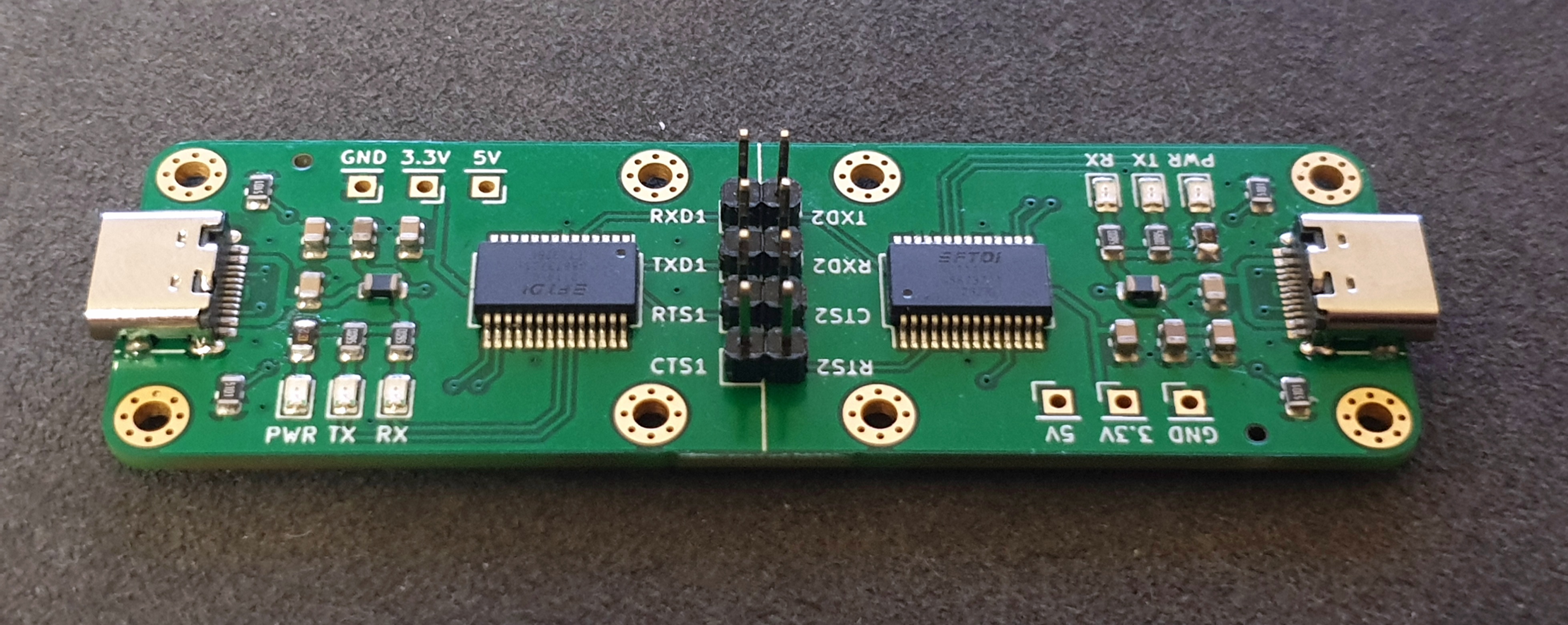
Bridge converting USB-C to serial (TTL) back to USB-C.
Serial bridge is an open-source printed circuit board by qzed, from the qzed/usb-serial-bridge repository on GitHub, published under the MIT licence. It is a 2-layer board of 80 × 25 mm with 48 parts on 55 nets, routed with 267 tracks and 45 vias.
It is built around the FT232RL. Its parts include 10 resistors, 8 capacitors, 6 diodes and 2 connectors. It belongs with the interfaces and adapters boards of this library.
Bridge converting USB-C to serial (TTL) back to USB-C. Useful for debugging Linux on devices without easily accessible serial ports.
Requirements:
=y) or the initramfs to enable early support at boot.Usage:
minicom:
minicom --device /dev/ttyUSBn --baudrate 115200/dev/ttyUSBn device, where n stands for the device number of the serial bridge on the host.console=ttyUSBn,115200 console=tty0console=tty0 is optional.
This causes the main console to be allocated on the client itself, otherwise you will get no output on that device.
If you wish for the main console to be on the USB-serial device, you can switch those statements.
Again make sure to replace n with the correct device number (usually 0 assuming you have no other USB-serial device connected).You can replace the baud rate (115200) with your desired one, however, make sure that it is set identically on both devices.
For further options see the respective kernel parameter documentation and the manpages for minicom.
| Qty | Value | Footprint | References |
|---|---|---|---|
| 6 | 560R | Resistor_SMD:R_0805_2012Metric | R1, R2, R3, R4, R5, R6 |
| 6 | LED | LED_SMD:LED_0805_2012Metric | D1, D2, D3, D4, D5, D6 |
| 6 | TestPoint | Connector_PinHeader_2.54mm:PinHeader_1x01_P2.54mm_Vertical | TP1, TP2, TP3, TP4, TP5, TP6 |
| 4 | 100nF | Capacitor_SMD:C_0805_2012Metric | C1, C2, C3, C4 |
| 4 | 5.1kR | Resistor_SMD:R_0805_2012Metric | R7, R8, R9, R10 |
| 2 | 10nF | Capacitor_SMD:C_0805_2012Metric | C7, C8 |
| 2 | 4.7uF | Capacitor_SMD:C_0805_2012Metric | C5, C6 |
| 2 | FT232RL | Package_SO:SSOP-28_5.3x10.2mm_P0.65mm | FT1, FT2 |
| 2 | USB_C_Receptacle_USB2.0 | Connector_USB:USB_C_Receptacle_HRO_TYPE-C-31-M-12 | J1, J2 |
| 2 | el | Inductor_SMD:L_0805_2012Metric | FB1, FB2 |
| 1 | J_CTS1/RTS2 | Connector_PinHeader_2.54mm:PinHeader_1x02_P2.54mm_Vertical | JP1 |
| 1 | J_RTS1/CTS2 | Connector_PinHeader_2.54mm:PinHeader_1x02_P2.54mm_Vertical | JP2 |
| 1 | J_RXD1/TXD2 | Connector_PinHeader_2.54mm:PinHeader_1x02_P2.54mm_Vertical | JP3 |
| 1 | J_TXD1/RXD2 | Connector_PinHeader_2.54mm:PinHeader_1x02_P2.54mm_Vertical | JP4 |
The 40 most common of 48 parts.
It measures 80 × 25 mm and has 2 copper layers, 1.6 mm thick.
48 parts, built around the FT232RL. The full list of its parts is on this page, with links to each part's symbol and footprint where PCBKit's library has them.
From the qzed/usb-serial-bridge repository on GitHub, at the commit this page was made from: the board is serial-bridge.kicad_pcb and its schematic serial-bridge.kicad_sch. PCBKit opens the board in the browser, with nothing to install.
Its repository publishes it under the MIT licence: you may reuse it on that licence's terms (keep the author's notice, and for a copyleft licence share your changes alike).
zmaker/arduino_cookbook
gli sketch del nuovo progetto Arduino Cookbook e dei video di YouTube


Ledger-Donjon/silicon-toaster
SiliconToaster is an open-source hardware electromagnetic fault injection device, designed for hardware security research. It has the following features:


jsjolund/dmx512-controller-board
Controller board for DMX512 compatible devices, built around the STM32F4 processor
