2 layers284.7 × 94.2 mm

 Quphoria/BenchATX1
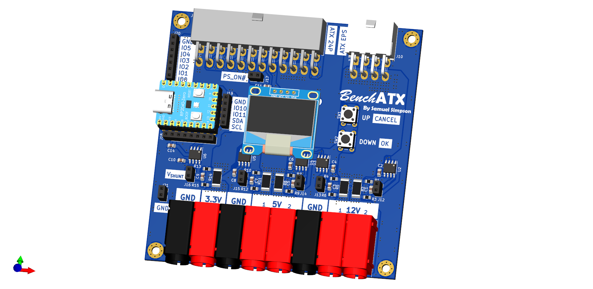
Breakout board for ATX PSU with current sensors
ATX PSU Bench Supply is an open-source printed circuit board by Quphoria, from the Quphoria/BenchATX repository on GitHub. It is a 4-layer board of 100 × 100 mm with 70 parts on 49 nets, routed with 584 tracks and 638 vias.
It is built around the TLV75733PDBV, RP2040-ZERO and 50C02CH-TL-E. Its parts include 21 resistors, 21 connectors, 14 capacitors, 7 ICs and 2 switches. It belongs with the power and sensors and measurement boards and the RP2040 boards of this library.


Bench power supply using an ATX PSU with current sensors
| Qty | Value | Footprint | References |
|---|---|---|---|
| 12 | 0.1uF | Capacitor_SMD:C_0805_2012Metric_Pad1.18x1.45mm_HandSolder | C1, C2, C3, C4, C5, C6, C7, C8, C9, C10, C13, C14 |
| 10 | 10 | Resistor_SMD:R_0805_2012Metric_Pad1.20x1.40mm_HandSolder | R1, R3, R4, R6, R7, R9, R10, R12, R13, R15 |
| 7 | Conn_01x02 | Connector_PinSocket_2.54mm:PinSocket_1x02_P2.54mm_Vertical | J12, J13, J14, J15, J16, J17, J21 |
| 5 | 0.005 | Resistor_SMD:R_2512_6332Metric_Pad1.40x3.35mm_HandSolder | R2, R5, R8, R11, R14 |
| 5 | 4mm Banana Socket R | LIB_24.243.1:24.243.1 | J1, J2, J4, J5, J7 |
| 5 | INA219BIDR | Package_SO:SOIC-8_3.9x4.9mm_P1.27mm | U2, U3, U4, U5, U6 |
| 4 | MountingHole_Pad | MountingHole:MountingHole_3.2mm_M3_Pad_Via | H1, H2, H3, H4 |
| 3 | 1.65k | Resistor_SMD:R_0805_2012Metric_Pad1.20x1.40mm_HandSolder | R16, R17, R19 |
| 3 | 4mm Banana Socket B | LIB_24.243.1:24.243.2 | J3, J6, J8 |
| 2 | 1uF | Capacitor_SMD:C_0805_2012Metric_Pad1.18x1.45mm_HandSolder | C11, C12 |
| 2 | SW_Push | Button_Switch_THT:SW_PUSH_6mm | SW1, SW2 |
| 1 | 1k | Resistor_SMD:R_0805_2012Metric_Pad1.20x1.40mm_HandSolder | R18 |
| 1 | 220 | Resistor_SMD:R_0805_2012Metric_Pad1.20x1.40mm_HandSolder | R21 |
| 1 | 3.3k | Resistor_SMD:R_0805_2012Metric_Pad1.20x1.40mm_HandSolder | R20 |
| 1 | 50C02CH-TL-E | Package_TO_SOT_SMD:SOT-23_Handsoldering | Q1 |
| 1 | Conn_01x05 | Connector_PinSocket_2.54mm:PinSocket_1x05_P2.54mm_Vertical | J19 |
| 1 | Conn_01x07 | Connector_PinSocket_2.54mm:PinSocket_1x07_P2.54mm_Vertical | J20 |
| 1 | Conn_01x08 | Connector_PinSocket_2.54mm:PinSocket_1x08_P2.54mm_Vertical | J18 |
| 1 | Molex 172448-0008 | Connector_Molex:Molex_Mini-Fit_Jr_5569-08A2_2x04_P4.20mm_Horizontal | J10 |
| 1 | Molex 39-30-1240 | Connector_Molex:Molex_Mini-Fit_Jr_5569-24A2_2x12_P4.20mm_Horizontal | J9 |
| 1 | OLED-128x64 | KLEEB_display:OLED-128x64 | J11 |
| 1 | TLV75733PDBV | Package_TO_SOT_SMD:SOT-23-5 | U7 |
| 1 | rp2040-zero | KLEEB_mcu:rp2040-zero-tht | U1 |
It measures 100 × 100 mm and has 4 copper layers, 1.6 mm thick.
70 parts, built around the TLV75733PDBV, RP2040-ZERO and 50C02CH-TL-E. The full list of its parts is on this page, with links to each part's symbol and footprint where PCBKit's library has them.
From the Quphoria/BenchATX repository on GitHub, at the commit this page was made from: the board is ATX PSU Bench Supply.kicad_pcb and its schematic ATX PSU Bench Supply.kicad_sch. PCBKit opens the board in the browser, with nothing to install.
Its repository states no licence, so its author keeps all rights: ask Quphoria before reusing the design.

azmat-bilal/bldc_motor_controller_pcb
A Brushless DC Motor controller board. The design is inspired and is compatible with Odrive project (https://github.com/madcowswe/ODriveHardware) except that this one has a single channel.


joeltroughton/nanoAmmeter
A small ammeter for measuring printed glucose biosensors

ccadic/HackZeGarage
ESP32-S2 and CC1101S 433Mhz usb stick to record and send car gates/garages data keys and open stuff

transportkollektiv/feuchtraumabzweigdose
A custom GPS Tracker with LoRaWAN/TTN intended for use on a bicycle

4rynv/Eklavya_Gantry
an attempt to automate screwing out and in of screw holes arranged in a matrix formation