
2 layers238.1 × 76.2 mm
Chai45HE
gohanda11/Chai45HE
Chai45HE is a 40% Hall-effect keyboard based on the HE60 project. This is a modified version that adapts the original 60% design to a compact 40% layout.
228 parts1GPL-3.0

60% Hall-effect keyboard
HE60 is an open-source printed circuit board by peppapighs, from the peppapighs/HE60 repository on GitHub, published under the GPL-3.0 licence. It is a 2-layer board of 284.7 × 94.2 mm with 332 parts on 140 nets, routed with 1,787 tracks and 2,123 vias.
It is built around the MT9102ET, AT32F405RCT7 and TLV75733PDBV, with the USBLC6-2SC6, XC6206P332MR-G and SN74LV4051AD among its other parts. Its parts include 160 capacitors, 4 resistors, 4 ICs, 3 connectors and 2 switches. It belongs with the keyboards and input boards of this library.


HE60 is a 60% Hall-effect keyboard PCB with 8kHz polling rate, a split spacebar and Tsangan layout support.
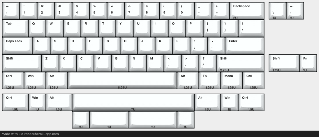
The following files are required:
Note that the components in the BOM are all mounted on the bottom side of the PCB, and are based on the available components in JLCPCB at the time of writing. You may need to adjust the components based on your preference or availability. For the JST connector (labeled JST_SH), I used WAFER-SH1.0-4PWB offered by JLCPCB. Make sure to deselect the USB-C port when choosing the components to solder if you are using the gummy O-ring version.
You may change the Hall-effect sensors during the component selection based on your preference, and availability. Different sensors require different calibration values, which can be adjusted using the web-based configurator. Different sensors may also have different polarity, and may require output inversion. Here are some options that I have used:
The fabrication files above are available here.
The following items are required to build the PCB:
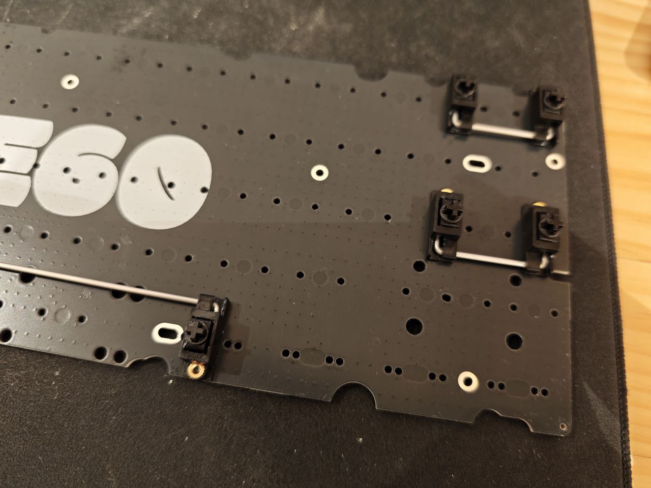
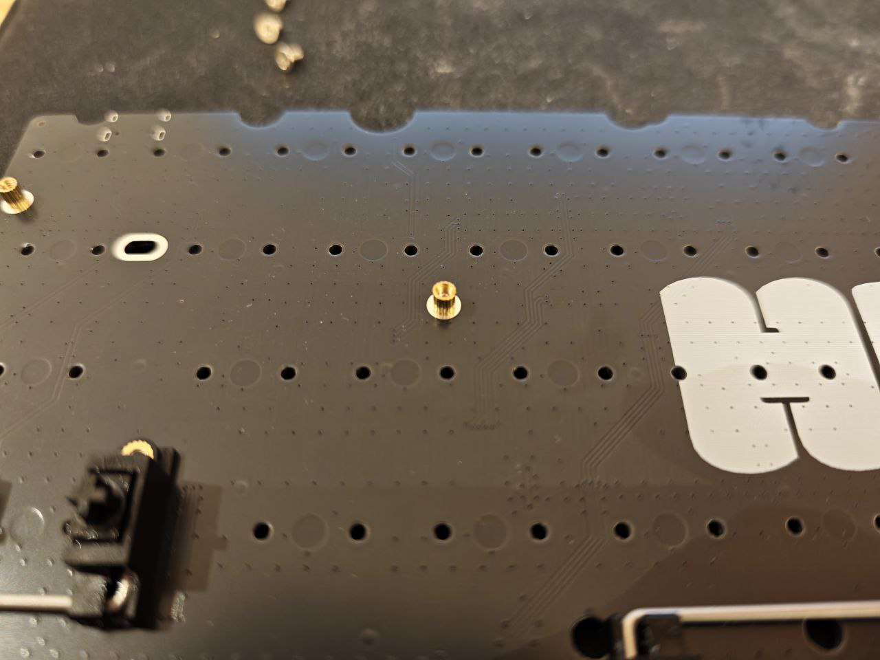
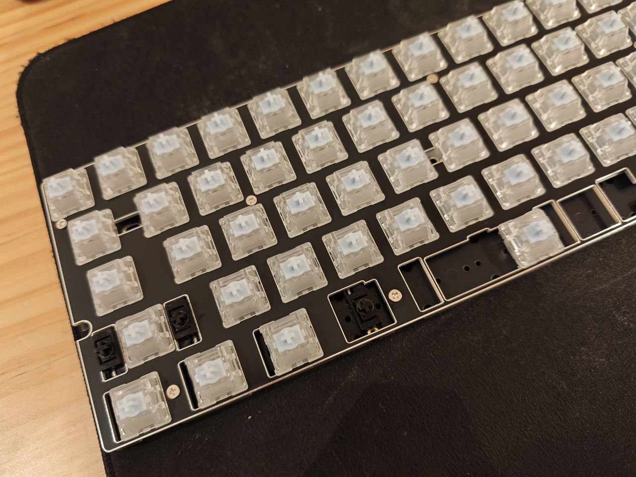

Head to libhmk for a pre-compiled firmware. The firmware can be flashed using DFU mode, which can be entered by holding the BOOT button before plugging in. You may need to install the DFU bootloader driver using Zadig. See libhmk for more information for firmware flashing instructions.
Important: The firmware assumes the Hall-effect sensors are MT9102ET, which does not require output inversion. If you are using other sensors with different polarity, you may need to invert the output, configured by the flag invert_adc in libhmk/keyboards/he60-v2/keyboard.json, and compile the firmware from source.
| Qty | Value | Footprint | References |
|---|---|---|---|
| 83 | 100n | Capacitor_SMD:C_0402_1005Metric | C1, C11, C101, C103, C105, C107, C109, C111, C113, C115, C117, C119, C121, C123, C125, C127 +67 |
| 69 | 4.7n | Capacitor_SMD:C_0402_1005Metric | C10, C12, C100, C102, C104, C106, C108, C110, C112, C114, C116, C118, C120, C122, C124, C126 +53 |
| 69 | MT9102ET | Package_TO_SOT_SMD:SOT-23-3 | HE1, HE2, HE10, HE11, HE12, HE13, HE14, HE15, HE16, HE17, HE18, HE19, HE20, HE21, HE22, HE23 +53 |
| 53 | 1U | HE60:MX-1U | MX1, MX2, MX10, MX11, MX12, MX13, MX14, MX16, MX18, MX19, MX20, MX21, MX22, MX23, MX24, MX25 +37 |
| 9 | SN74LV4051A | Package_SO:TSSOP-16_4.4x5mm_P0.65mm | AM1, AM2, AM3, AM4, AM5, AM6, AM7, AM8, AM9 |
| 7 | 1.25U | HE60:MX-1.25U | MX58, MX60, MX62, MX70, MX72, MX74, MX76 |
| 6 | 1.5U | HE60:MX-1.5U | MX17, MX30, MX59, MX63, MX71, MX75 |
| 4 | 2.2u | Capacitor_SMD:C_0603_1608Metric | C148, C149, C150, C151 |
| 2 | 1.75U | HE60:MX-1.75U | MX31, MX55 |
| 2 | 12k | Resistor_SMD:R_0402_1005Metric | R3, R4 |
| 2 | 2.25U | HE60:MX-2.25U | MX43, MX44 |
| 2 | 30p | Capacitor_SMD:C_0603_1608Metric | C152, C153 |
| 2 | 5.1k | Resistor_SMD:R_0402_1005Metric | R1, R2 |
| 2 | TS-1187A-B-A-B | Button_Switch_SMD:SW_Push_1P1T_XKB_TS-1187A | SW1, SW2 |
| 2 | ToolingHole | HE60:ToolingHole | TH1, TH2 |
| 1 | 10u | Capacitor_SMD:C_0603_1608Metric | C157 |
| 1 | 1u | Capacitor_SMD:C_0603_1608Metric | C159 |
| 1 | 2.25U | HE60:MX-2.25U-ReversedStabilizers | MX65 |
| 1 | 2.75U | HE60:MX-2.75U-ReversedStabilizers | MX68 |
| 1 | 2.75U | HE60:MX-2.75U | MX56 |
| 1 | 2U | HE60:MX-2U | MX15 |
| 1 | 6.25U | HE60:MX-6.25U-ReversedStabilizers | MX66 |
| 1 | 7U | HE60:MX-7U-ReversedStabilizers | MX67 |
| 1 | AT32F405RCT7 | Package_QFP:LQFP-64_10x10mm_P0.5mm | U4 |
| 1 | BSMD0805-050-24V | Fuse:Fuse_0805_2012Metric | F1 |
| 1 | H60 | HE60:H60 | PCB1 |
| 1 | JST_SH | Connector_JST:JST_SH_SM04B-SRSS-TB_1x04-1MP_P1.00mm_Horizontal | J2 |
| 1 | TC2030 | Connector:Tag-Connect_TC2030-IDC-FP_2x03_P1.27mm_Vertical | J3 |
| 1 | TLV75733PDBV | Package_TO_SOT_SMD:SOT-23-5 | U2 |
| 1 | TYPE-C-31-M-12 | Connector_USB:USB_C_Receptacle_HRO_TYPE-C-31-M-12 | J1 |
| 1 | USBLC6-2SC6 | Package_TO_SOT_SMD:SOT-23-6 | U1 |
| 1 | X322512MSB4SI | Crystal:Crystal_SMD_3225-4Pin_3.2x2.5mm | Y1 |
| 1 | XC6206P332MR-G | Package_TO_SOT_SMD:SOT-23-3 | U3 |
It measures 284.7 × 94.2 mm and has 2 copper layers, 1.6 mm thick.
332 parts, built around the MT9102ET, AT32F405RCT7, TLV75733PDBV and USBLC6-2SC6. The full list of its parts is on this page, with links to each part's symbol and footprint where PCBKit's library has them.
From the peppapighs/HE60 repository on GitHub, at the commit this page was made from: the board is HE60/HE60.kicad_pcb and its schematic HE60/HE60.kicad_sch. PCBKit opens the board in the browser, with nothing to install.
Its repository publishes it under the GPL-3.0 licence: you may reuse it on that licence's terms (keep the author's notice, and for a copyleft licence share your changes alike).
gohanda11/Chai45HE
Chai45HE is a 40% Hall-effect keyboard based on the HE60 project. This is a modified version that adapts the original 60% design to a compact 40% layout.


gohanda11/Split60HE
Split60HE is a split (left/right) version of the 60% Hall-effect keyboard HE60, designed in KiCad.


peppapighs/M256-WHE
M256-WHE is a Hall-effect keyboard PCB, specifically designed for Mode Encore, Mode SixtyFive v2, and Mode Envoy [1].


Mokeded/Symm60HE
Symmetrical Hall effect Alice keyboard based off of the Doe
