2 layers380 × 148.5 mm

 QinCai-rui/SmartClockPi1
A Raspberry Pi Zero 2 W based smart clock with touchscreen display, environmental sensing, and internet weather integration.
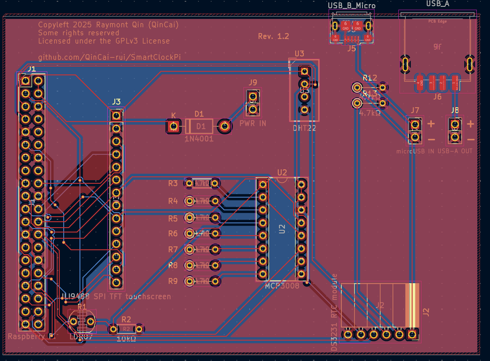
SmartClockPi is an open-source printed circuit board by QinCai-rui, from the QinCai-rui/SmartClockPi repository on GitHub, published under the GPL-3.0 licence. It is a 2-layer board of 94.5 × 67.1 mm with 29 parts on 49 nets, routed with 226 tracks and 17 vias.
It is built around the DHT22 and MCP3008-I/P. Its parts include 11 resistors, 8 connectors, 2 ICs and 1 diode.


A Raspberry Pi Zero 2 W based smart clock with touchscreen display, environmental sensing, and internet weather integration.
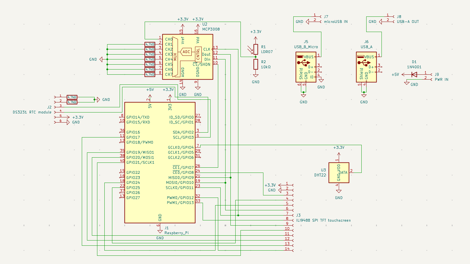
This project uses KiCad for PCB design. The files are located in the PCB/ directory. You can open them with KiCad to view the schematics and PCB layout. These are the screenshots of the PCB and schematics:
| Component | Description | Quantity | Link | Price | Shipping | Est. price (exl. GST) | Est. price (inc. GST) |
|---|---|---|---|---|---|---|---|
| Raspberry Pi Zero 2 W | Main controller/computer of the project | 1 | https://www.aliexpress.com/item/1005007899652009.html | $15.00 | $0.00 | $15.00 | $17.25 |
| ILI9488 3.5" SPI TFT Touchscreen | 480x320 pixel color LCD with resistive touch input, using SPI interface; displays the clock and all UI elements. | 1 | https://www.aliexpress.com/item/1005007096645415.html | $12.34 | $0.00 | $12.34 | $14.19 |
| DHT22 Sensor | provides indoor environmental readings | 1 | https://www.aliexpress.com/item/32759901711.html | $2.05 | $0.00 | $2.05 | $2.36 |
| 1x14 Pin Socket Header | Single-row, female 2.54mm pitch header; connects the TFT display module to the PCB. | 1 (pack of 10, use 1) | https://www.aliexpress.com/item/4001198421663.html | $1.99 | $0.00 | $1.99 | $2.29 |
| 1x6 Pin Socket Header | Single-row, female 2.54mm pitch header; connects the DAC to the PCB. | 1 (pack of 10, use 1) | https://www.aliexpress.com/item/4001198421663.html | $1.70 | $0.00 | $1.70 | $1.96 |
| 1x6 Pin Socket Header Right angled | Single-row, female 2.54mm pitch, right angle header; connects the RTC module to the PCB. | 1 (pack of 5, use 1) | https://www.aliexpress.com/item/1005008210852764.html | $1.64 | $0.00 | $1.64 | $1.89 |
| 1x4 Pin Socket Header | Single-row, female 2.54mm pitch header; connects the DHT22 to the PCB. | 1 (pack of 10, use 1) | https://www.aliexpress.com/item/4001198421663.html | $1.69 | $0.00 | $1.69 | $1.94 |
| Photoresistor | for automatic display brightness adjustment. 5528 | 1 (pack of 50, use 1) | https://www.aliexpress.com/item/1005002145052802.html | $1.66 | $1.68 | $3.34 | $3.84 |
| MCP3008 (DIP) | 8-channel, 10-bit ADC with SPI interface; reads analog sensors like photoresistors. | 3 (use 1) | https://www.digikey.co.nz/en/products/detail/microchip-technology/MCP3008-I-P/319422 | $9.36 | $0.00 | $9.36 | $10.76 |
| DS3231 RTC (module) | Real-time clock module with battery backup; keeps accurate time when Pi is powered off (or when my internet connection dies) | 1 | https://www.aliexpress.com/item/1005008172587774.html | $1.70 | $0.00 | $1.70 | $1.96 |
| DIP-16 IC socket | For MCP3008 (DIP) | 1 (pack of 10, use 1) | https://www.aliexpress.com/item/1005009030108697.html | $0.60 | $1.63 | $2.23 | $2.56 |
| LIR3032 cell | 3.6V Lithium Battery Rechargeable Battery | 1 (pack of 2, use 1) | https://www.aliexpress.com/item/1005009124669879.html | $7.17 | $0.00 | $7.17 | $8.25 |
| micro-USB port | Power input | 5 (use 1) | https://www.digikey.co.nz/en/products/detail/amphenol-cs-fci/10118193-0001LF/2785388 | $2.15 | $0.00 | $2.15 | $2.47 |
| USB-A port | Power output (from battery charger) | 5 (use 1) | https://www.digikey.co.nz/en/products/detail/gct/USB1046-GF-0190-L-B-A/10649632 | $3.65 | $0.00 | $3.65 | $4.20 |
| 18650 Lithium Battery Charger | 5V 2.4A Dual USB OUT | 1 (pack of 2, use 1) | https://www.aliexpress.com/item/1005006839030660.html | $6.77 | $0.00 | $6.77 | $7.79 |
| microSD card | 64GB | 2 (use 1) | https://www.digikey.co.nz/en/products/detail/raspberry-pi/SC1629/24627140 | $12.98 | $0.00 | $12.98 | $14.93 |
| Diode | 1N4001 | 100 | https://www.digikey.co.nz/en/products/detail/diotec-semiconductor/1N4001/13164614 | $4.66 | $0.00 | $4.66 | $5.36 |
| USB speaker | 1 | https://www.aliexpress.com/item/1005007586786674.html | $4.52 | $8.20 | $12.72 | $14.63 | |
| TOTAL | $103.14 | $118.61 |
I wanted a smart clock that could display the time, date, indoor temperature, humidity, and outdoor weather conditions. I also wanted it to have a touchscreen interface for easy interaction. The Raspberry Pi Zero 2 W was chosen for its compact size and sufficient processing power for this project.
"Why don't you just buy a pre-made smart clock?" you might ask. Well, I wanted to learn more about PCB layout/designing. This project is a great way to "exercise" while creating something useful for myself.
Also, I wanted to make it modular so I can easily swap out components or add new features in the future. The custom PCB design allows for easy connections and modifications.
Please see SmartClockPi-bom.csv (Created since this is required for Highway)
luma.lcd for display controladafruit-circuitpython-bme280 for sensor interfacePillow for graphics renderingSmartClockPi/
├── README.md
├── JOURNAL.md # Development journal with progress updates
├── SmartClockPi-bom.csv # Bill of Materials
├── PCB/ # KiCad PCB design files
│ ├── smartclockpi.kicad_pro
│ ├── smartclockpi.kicad_sch
│ ├── smartclockpi.kicad_pcb
│ └── Gerber/ # Manufacturing files
└── [Software files to be added]CAD/ directory.This project is Free and Open-source, licensed under the GPLv3 license. Feel free to contribute or use it for your own projects!
See LICENSE for more details.
| Qty | Value | Footprint | References |
|---|---|---|---|
| 9 | 4.7kΩ | Resistor_THT:R_Axial_DIN0204_L3.6mm_D1.6mm_P5.08mm_Horizontal | R3, R4, R5, R6, R7, R8, R9, R12, R13 |
| 1 | 10kΩ | Resistor_THT:R_Axial_DIN0204_L3.6mm_D1.6mm_P5.08mm_Horizontal | R2 |
| 1 | 1N4001 | Diode_THT:D_DO-41_SOD81_P10.16mm_Horizontal | D1 |
| 1 | DHT22 | Sensor:Aosong_DHT11_5.5x12.0_P2.54mm | U3 |
| 1 | DS3231 RTC module | Connector_PinSocket_2.54mm:PinSocket_1x06_P2.54mm_Horizontal | J2 |
| 1 | ILI9488 SPI TFT touchscreen | Connector_PinSocket_2.54mm:PinSocket_1x14_P2.54mm_Vertical | J3 |
| 1 | LDR07 | OptoDevice:R_LDR_5.2x5.2mm_P3.5mm_Horizontal | R1 |
| 1 | MCP3008 | Package_DIP:DIP-16_W7.62mm_Socket | U2 |
| 1 | PWR IN | Connector_PinSocket_2.54mm:PinSocket_1x02_P2.54mm_Vertical | J9 |
| 1 | Raspberry_Pi | Connector_PinHeader_2.54mm:PinHeader_2x20_P2.54mm_Vertical | J1 |
| 1 | USB-A OUT | Connector_PinSocket_2.54mm:PinSocket_1x02_P2.54mm_Vertical | J8 |
| 1 | USB_A | Connector_USB:USB_A_Receptacle_GCT_USB1046 | J6 |
| 1 | USB_B_Micro | Connector_USB:USB_Micro-B_Amphenol_10118193-0001LF_Horizontal | J5 |
| 1 | microUSB IN | Connector_PinSocket_2.54mm:PinSocket_1x02_P2.54mm_Vertical | J7 |
The 22 most common of 29 parts.

cyberboy666/recurBOY
a rpi0 video-instrument – created in collaboration with Guergana Tzatchkova

nekonaute/pogobot
Pogobot is an open-source open-hardware robotic platform for swarm robotics

cyberboy666/i_n_c_u_r
a r_e_c_u_r video sampler extension circuit - adding knobs, cv and serial midi control


IceyPlazza/EWB-EPA-Rainworks
26-27 EWB EPA Rainworks project; We're putting a sensor box in the ground!

butterstick-fpga/programming-jig
A FT232H based production programming jig for the ButterStick

challengerjdb/RaspberryPiHat-datalogger
My name is Jacob Bendell, and I’m a student at the University of Pennsylvania studying Electrical Engineering. I took this past year off from school to avoid online classes and intern at Amped Innovation, a start-up in…
It measures 94.5 × 67.1 mm and has 2 copper layers, 1.6 mm thick.
29 parts, built around the DHT22 and MCP3008-I/P. The full list of its parts is on this page, with links to each part's symbol and footprint where PCBKit's library has them.
From the QinCai-rui/SmartClockPi repository on GitHub, at the commit this page was made from: the board is PCB/smartclockpi.kicad_pcb and its schematic PCB/smartclockpi.kicad_sch. PCBKit opens the board in the browser, with nothing to install.
Its repository publishes it under the GPL-3.0 licence: you may reuse it on that licence's terms (keep the author's notice, and for a copyleft licence share your changes alike).