8 layers80 × 80 mm

 qfreiman/qsbc-zero1
Single Board Computer based on the i.MX6ULL
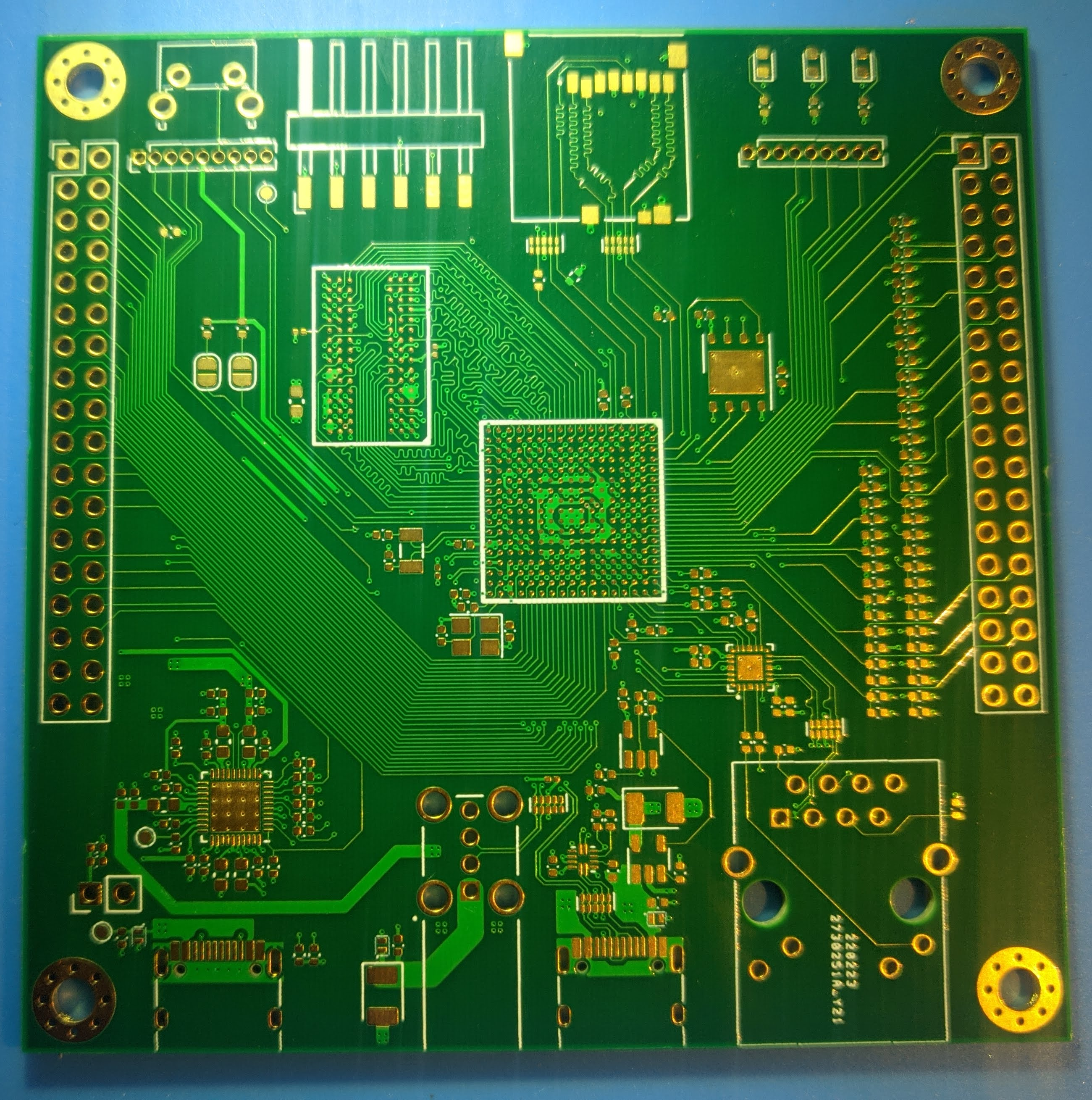
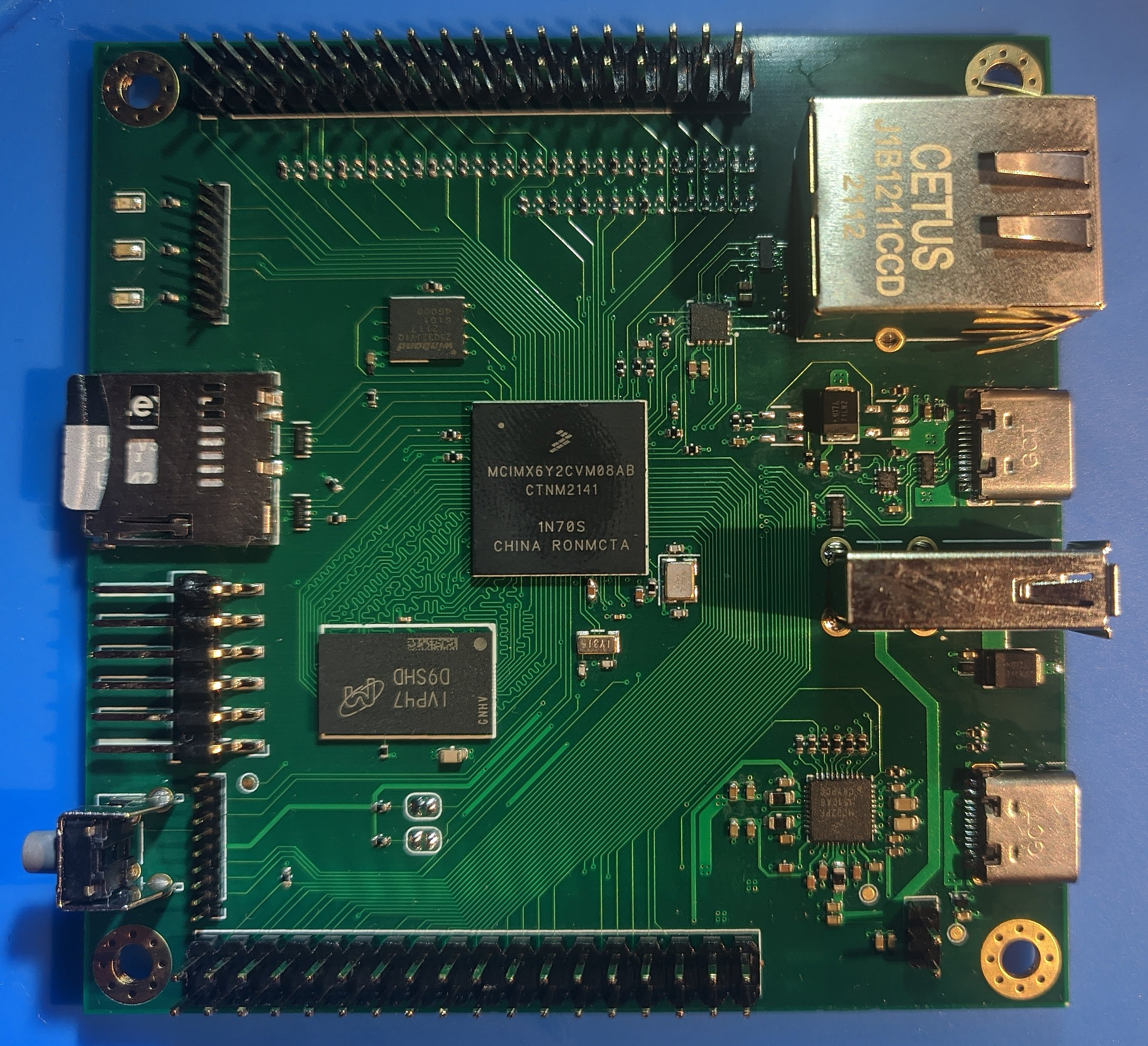
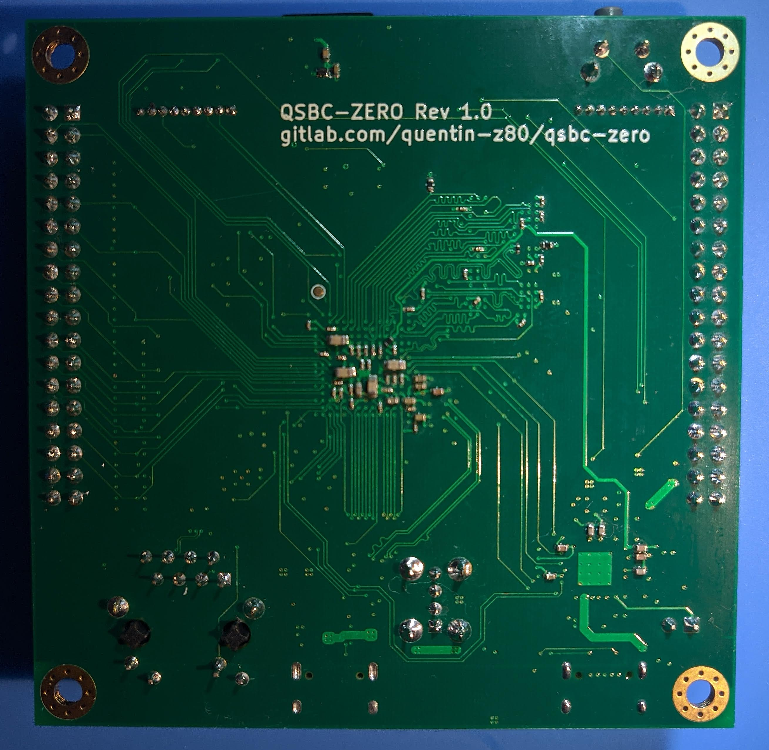
Qsbc zero is an open-source printed circuit board by qfreiman, from the qfreiman/qsbc-zero repository on GitHub, published under the GPL-3.0 licence. It is a 4-layer board of 80 × 80 mm with 243 parts on 274 nets, routed with 4,227 tracks and 578 vias.
It is built around the MCIMX6Y2DVM09AB, DP83825IRMQR and TUSB320LAIRWBR, with the W25Q32JVZPIQ, MEM2051-00-195-00-A and TPD4EUSB30DQAR among its other parts. Its parts include 105 capacitors, 91 resistors, 17 ICs, 11 connectors and 3 diodes. It belongs with the computers and single-board computers boards of this library.


Specs:
Manufactured using JLCPCB's JLC2116 stackup
Build imx_usb_loader
git clone git@github.com:boundarydevices/imx_usb_loader.git
cd imx_usb_loader
make
Build u-boot
git clone git@gitlab.com:quentin-z80/u-boot.git
cd u-boot
export CROSS_COMPILE=arm-linux-gnueabi- ARCH=arm
make qsbc-zero_defconfig
make
Build qspi-header
cd tools/qspi-header
./qspi-header.sh qspi-nor-winbond-w25q32jv-config qspi-config.bin
Connect to board over serial and load u-boot over usb
screen /dev/ttyUSB0 115200
./imx_usb_loader /path/to/u-boot/u-boot-dtb.imx
Transfer qspi-header over XMODEM or any other method and flash
sf probe
sf erase 0x0 0x400000
loadx
in screen hit Ctrl-A followed by :
exec !! sx /path/to/qspi-header/qspi-config.bin
sf write $loadaddr 0x400 $filesize
Transfer u-boot over XMODEM or any other method and flash
loadxin screen hit Ctrl-A followed by :
exec !! sx /path/to/u-boot/u-boot-dtb.imx
sf write $loadaddr 0x1000 $filesize
Blow fuses to boot from qspi
fuse prog -y 0 5 0x10 #BOOT_CFG1[4] = 1
fuse prog -y 0 6 0x10 #BT_FUSE_SEL = 1| Qty | Value | Footprint | References |
|---|---|---|---|
| 61 | 10K | Resistor_SMD:R_0402_1005Metric | R1, R10, R11, R14, R100, R101, R102, R103, R104, R105, R106, R107, R108, R109, R139, R140 +45 |
| 41 | 0.22uF | Capacitor_SMD:C_0201_0603Metric | C23, C24, C25, C26, C27, C28, C29, C30, C31, C32, C33, C34, C35, C36, C37, C38 +25 |
| 16 | 10uF | Capacitor_SMD:C_0402_1005Metric | C3, C13, C14, C15, C16, C18, C19, C20, C55, C60, C65, C76, C82, C84, C110, C111 |
| 13 | 0.1uF | Capacitor_SMD:C_0402_1005Metric | C1, C5, C66, C67, C68, C77, C78, C94, C95, C97, C106, C122, C123 |
| 13 | 1uF | Capacitor_SMD:C_0402_1005Metric | C6, C8, C9, C22, C56, C63, C64, C69, C88, C90, C96, C112, C113 |
| 7 | 22uF | Capacitor_SMD:C_0603_1608Metric | C2, C10, C11, C12, C41, C57, C62 |
| 7 | 4.7uF | Capacitor_SMD:C_0402_1005Metric | C17, C21, C42, C43, C87, C89, C91 |
| 6 | 100K | Resistor_SMD:R_0402_1005Metric | R6, R7, R8, R16, R23, R24 |
| 5 | 1K | Resistor_SMD:R_0402_1005Metric | R26, R128, R129, R133, R134 |
| 5 | TPD4EUSB30 | Package_SON:USON-10_2.5x1.0mm_P0.5mm | U6, U11, U25, U26, U27 |
| 4 | 0R | Resistor_SMD:R_0402_1005Metric | R22, R25, R40, R130 |
| 4 | D5V0H1B2LP | qsbc-zero:DFN100X60X45-2N | U7, U8, U13, U14 |
| 4 | MountingHole_Pad | MountingHole:MountingHole_3.2mm_M3_Pad_Via | H1, H2, H3, H4 |
| 4 | TestPoint | TestPoint:TestPoint_Pad_D1.0mm | TP3, TP4, TP6, TP26 |
| 3 | 18pF | Capacitor_SMD:C_0402_1005Metric | C72, C73, C109 |
| 3 | 1uH | Inductor_SMD:L_0603_1608Metric | L1, L2, L3 |
| 2 | 10R | Resistor_SMD:R_0402_1005Metric | R13, R55 |
| 2 | 16pF | Capacitor_SMD:C_0402_1005Metric | C70, C71 |
| 2 | 2.49K | Resistor_SMD:R_0402_1005Metric | R131, R132 |
| 2 | 240R | Resistor_SMD:R_0201_0603Metric | R2, R5 |
| 2 | 4.7K | Resistor_SMD:R_0402_1005Metric | R18, R19 |
| 2 | 5.1K | Resistor_SMD:R_0402_1005Metric | R41, R43 |
| 2 | Conn_01x09_Male | Connector_PinHeader_1.27mm:PinHeader_1x09_P1.27mm_Vertical | J8, J11 |
| 2 | Conn_02x18_Odd_Even | Connector_PinHeader_2.54mm:PinHeader_2x18_P2.54mm_Vertical | J5, J10 |
| 2 | Jumper_2_Open | Jumper:SolderJumper-2_P1.3mm_Open_RoundedPad1.0x1.5mm | JP1, JP2 |
| 2 | USB4105 | Connector_USB:USB_C_Receptacle_HRO_TYPE-C-31-M-12 | J2, J4 |
| 1 | 0.47uF | Capacitor_SMD:C_0402_1005Metric | C83 |
| 1 | 120uF | Capacitor_SMD:CP_Elec_6.3x4.9 | C93 |
| 1 | 1M | Resistor_SMD:R_0402_1005Metric | R9 |
| 1 | 2.2K | Resistor_SMD:R_0402_1005Metric | R114 |
| 1 | 2.2M | Resistor_SMD:R_0402_1005Metric | R12 |
| 1 | 2.2uF | Capacitor_SMD:C_0402_1005Metric | C7 |
| 1 | 24Mhz | Crystal:Crystal_SMD_3225-4Pin_3.2x2.5mm | Y1 |
| 1 | 32.768kHz | Crystal:Crystal_SMD_3215-2Pin_3.2x1.5mm | Y2 |
| 1 | 470R | Resistor_SMD:R_0201_0603Metric | R4 |
| 1 | 6.49K | Resistor_SMD:R_0402_1005Metric | R115 |
| 1 | 74LVC1G04 | Package_TO_SOT_SMD:SOT-23-5 | U12 |
| 1 | AP22811B | Package_TO_SOT_SMD:SOT-23-5 | U5 |
| 1 | Conn_01x02_Male | Connector_PinHeader_2.54mm:PinHeader_1x02_P2.54mm_Vertical | J9 |
| 1 | Conn_01x06_Male | Connector_Harwin:Harwin_M20-89006xx_1x06_P2.54mm_Horizontal | J7 |
| 1 | DP83825 | qsbc-zero:XCVR_DP83825IRMQR | U18 |
| 1 | J1B1211CCD | qsbc-zero:J1B1211CCD | J6 |
| 1 | LED_GREEN | LED_SMD:LED_0603_1608Metric | D1 |
| 1 | LED_ORANGE | LED_SMD:LED_0603_1608Metric | D2 |
| 1 | LED_YELLOW | LED_SMD:LED_0603_1608Metric | D3 |
| 1 | MC32PF1510A6EP | Package_DFN_QFN:QFN-40-1EP_5x5mm_P0.4mm_EP3.8x3.8mm_ThermalVias | U2 |
| 1 | MT41K256M16 | qsbc-zero:MICRON-FBGA-96 | U3 |
| 1 | MX6UL-VM | qsbc-zero:SOT1534-2 | U1 |
| 1 | Micro_SD_Card_Det1 | qsbc-zero:GCT_MEM2051-00-195-00-A_REVC | J1 |
| 1 | SW_Push | Button_Switch_THT:SW_Tactile_SPST_Angled_PTS645Vx58-2LFS | SW1 |
| 1 | TUSB320 | Package_DFN_QFN:Texas_X2QFN-12_1.6x1.6mm_P0.4mm | U4 |
| 1 | USB-A-S-F-B-VU | qsbc-zero:SAMTEC_USB-A-S-X-X-VU | J3 |
| 1 | W25Q512JVEIQ | Package_SON:WSON-8-1EP_6x5mm_P1.27mm_EP3.4x4.3mm | U9 |
It measures 80 × 80 mm and has 4 copper layers, 1.6 mm thick.
243 parts, built around the MCIMX6Y2DVM09AB, DP83825IRMQR, TUSB320LAIRWBR and W25Q32JVZPIQ. The full list of its parts is on this page, with links to each part's symbol and footprint where PCBKit's library has them.
From the qfreiman/qsbc-zero repository on GitHub, at the commit this page was made from: the board is qsbc-zero.kicad_pcb and its schematic boot.kicad_sch. PCBKit opens the board in the browser, with nothing to install.
Its repository publishes it under the GPL-3.0 licence: you may reuse it on that licence's terms (keep the author's notice, and for a copyleft licence share your changes alike).

antmicro/thunderbolt-pcie-adapter
This project contains open hardware design files for an adapter board wrapping 4-lane (i.e. 4x) PCIe Gen 3.0 devices into a Thunderbolt 3 uplink. It is based on the Intel/JHL6340SLLSQ Thunderbolt controller.

MicroType-Engineering/MTE_USB_HUB
As designed on the MicroType Engineering's YouTube series: https://youtu.be/uzqXgHHZUUs


Wierdwizard2587/Custom-Teensy-4.1-PCB-Design
Custom Designed MCU design based upon Teensy 4.1


