2 layers56.3 × 62.4 mm
Lm5116
xiaokaizip/lm5116-digital-power
c #define MCP41100ENABLE 0B00010011 #define MCP41100DISABLE 0B00100000
86 parts1

 QDU-Robomaster/TTLtoCAN
电源部分通过 TPS54202 将输入电源降压至设计目标 5V,再由 ME6211 产生板上 3.3V。STM32 连接 ToF 的 UART,并通过 CAN 收发器接入总线。通信转换需要配套固件,当前仓库未提供固件及协议定义。
TTLtoCANforTOF is an open-source printed circuit board by QDU-Robomaster, from the QDU-Robomaster/TTLtoCAN repository on GitHub. It is a 2-layer board of 33.5 × 17.1 mm with 44 parts on 56 nets, routed with 267 tracks and 61 vias.
It is built around the TCAN3413DRB, TD1469 and ME6211C33M5G-N, with the BZT52C12S, SI2309CDS-T1-GE3 and X32258MSB4SI among its other parts. Its parts include 17 capacitors, 9 resistors, 4 ICs, 4 connectors and 3 diodes. It belongs with the STM32 boards of this library.


TTLtoCANforTOF
面向 ToF 设备的 TTL UART 转 CAN 通信模块,设计目标是通过 24V 输入为 ToF 提供 5V 电源,并由 STM32 完成串口数据与 CAN 报文之间的转换。
以下预览基于 2026-10-05 21:07 保存的 PCB 文件重新生成。部分器件未配置三维模型,实际装配以封装和 BOM 为准。
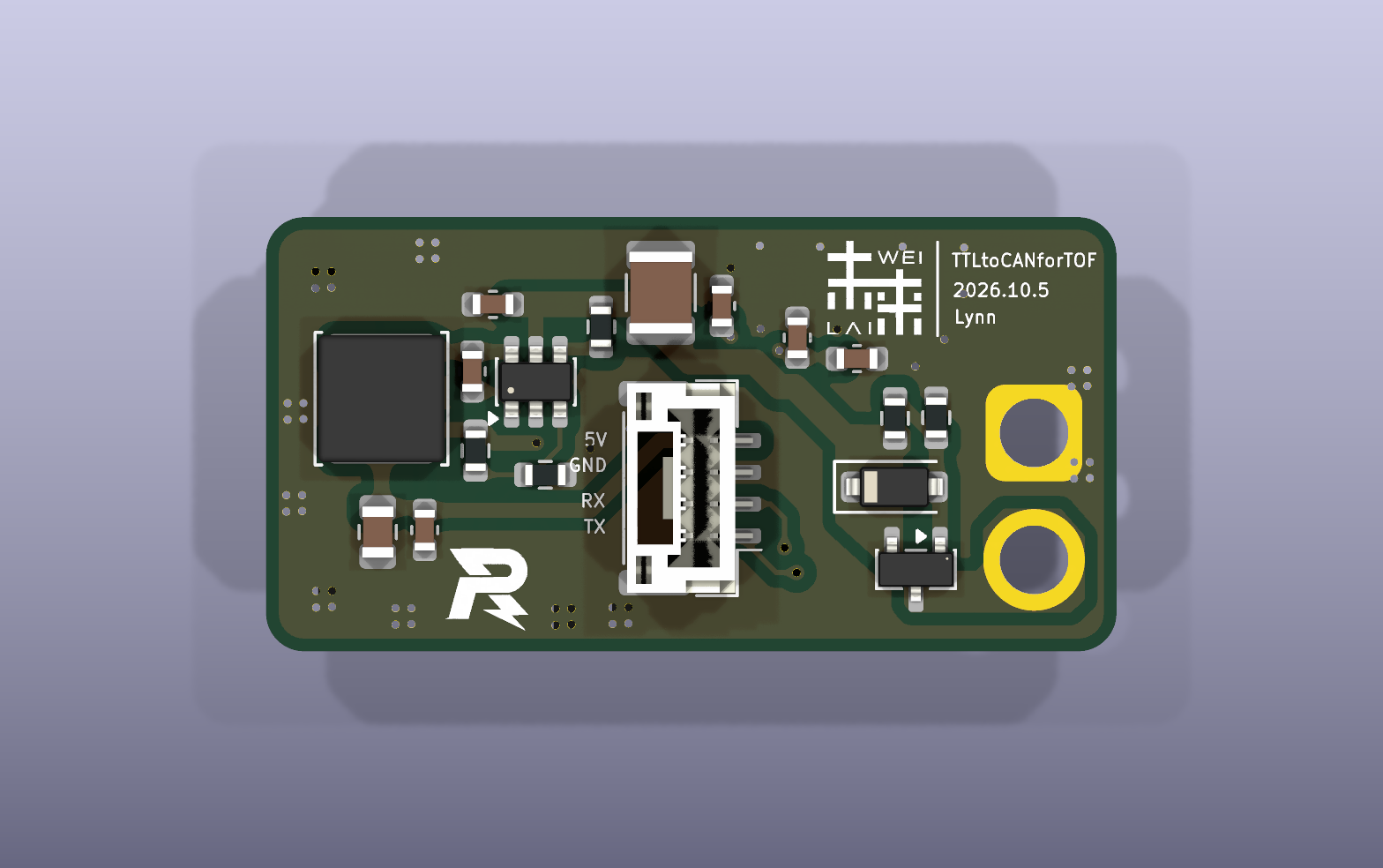
正面:
背面:
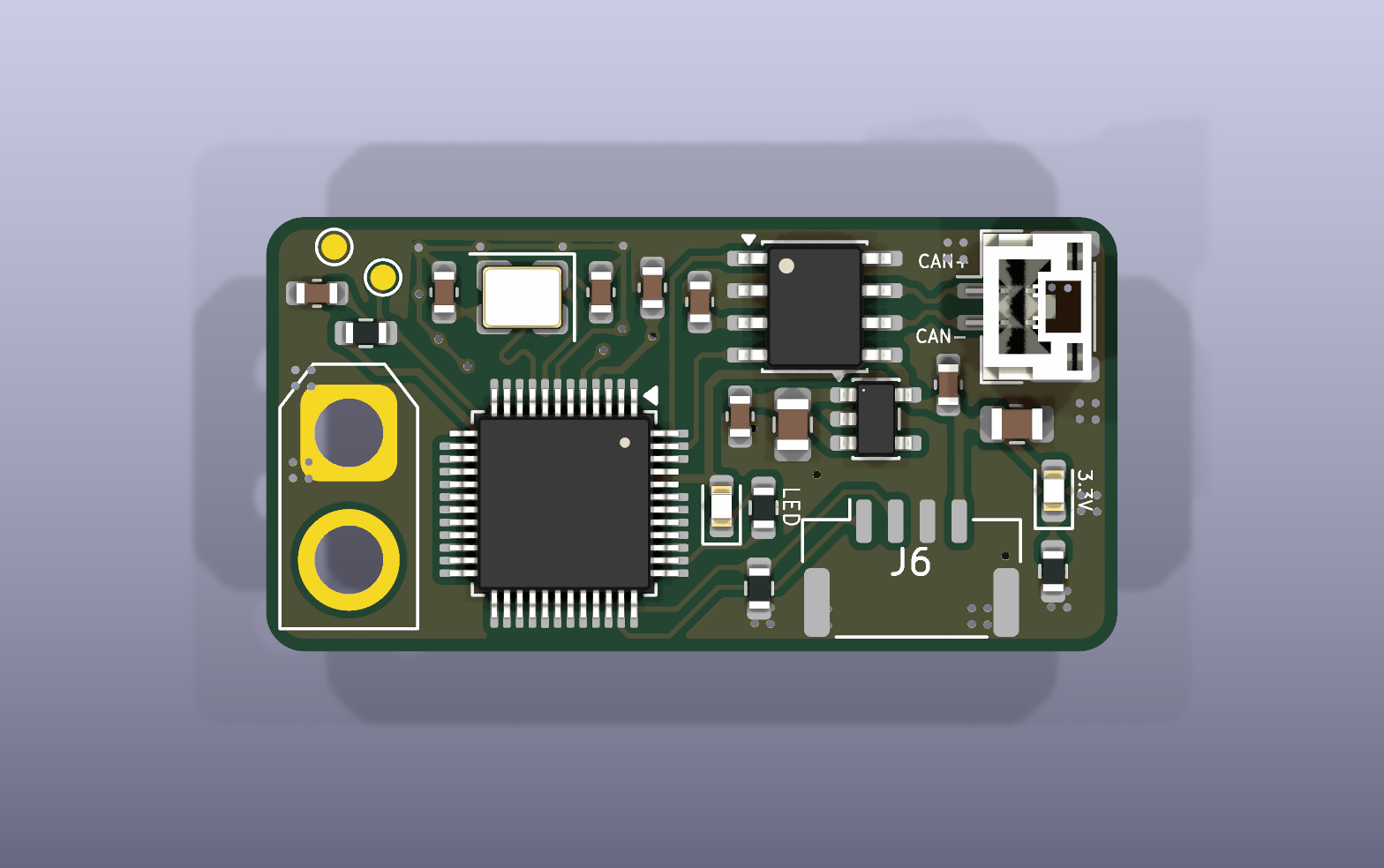
PCB 尺寸 36.00 × 20.05 mm,圆角矩形 层数 / 板厚 2 层 / 1.6 mm 输入电源 设计标称 24V,经 J4 输入 ToF 电源 设计目标 5V,经 J3 第 4 脚输出 板上逻辑电源 3.3V 主控 STM32G0B1CBTx,LQFP-48 通信接口 UART(J3)、CAN(J2) 调试接口 SWD(J6)
J4:电源输入 AMASS XT30U-F,2Pin
1:GND;
2:VCC_IN(标称 24V 输入)
J2:CAN JST GH,2Pin,1.25 mm
1:CAN− / CAN_L;
2:CAN+ / CAN_H
J3:ToF JST GH,4Pin,1.25 mm
1:USART1_TX(模块输出,接设备 RX);
2:USART1_RX(模块输入,接设备 TX);
3:GND;
4:5V 电源输出
J6:SWD Molex CLIK-Mate 502386-0470,4Pin,1.25 mm
1:SWDIO;
2:SWCLK;
3:GND;
4:3.3V 参考电源
电源部分通过 TPS54202 将输入电源降压至设计目标 5V,再由 ME6211 产生板上 3.3V。STM32 连接 ToF 的 UART,并通过 CAN 收发器接入总线。通信转换需要配套固件,当前仓库未提供固件及协议定义。
详细的接口接线、工程打开方式、生产资料与调试安排见 工程说明文档。
U1 TPS54202DDC 开关降压,设计用于产生 5V U2 ME6211C33M5 3.3V 线性稳压 U3 STM32G0B1CBTx 通信处理主控 U6 TCAN3413DR(当前 Value) CAN 收发器 Q2 Si2309CDS-T1-GE3 输入侧 P 沟道 MOS 管 D3 BZT52-C12 输入保护电路中的稳压管 L1 15µH 降压电感 Y1 X32258MSB MCU 外部晶振
制造和装配输出位于 Production_documents/,各子目录用途见 工程说明文档。 使用 KiCad 10.0.x 打开根目录的 TTLtoCANforTOF.kicad_pro,再进入原理图或 PCB 编辑器。 TTLtoCANforTOF.kicad_sch 当前原理图 TTLtoCANforTOF.kicad_pcb 当前 PCB sym-lib-table 项目符号库路径配置 BOM/ 设计物料清单 Documents/ 项目说明、预览图和检查报告 3Dmodel/TTLtoCANforTOF.step 整板 STEP 模型 Production_documents/ 生产输出资料 History/ 历史工程快照,不作为当前生产依据
| Qty | Value | Footprint | References |
|---|---|---|---|
| 10 | 0.1uF | Capacitor_SMD:C_0603_1608Metric | C1, C2, C10, C12, C13, C14, C18, C19, C20, C21 |
| 2 | 100kΩ | Resistor_SMD:R_0603_1608Metric | R7, R9 |
| 2 | 10kΩ | Resistor_SMD:R_0603_1608Metric | R6, R8 |
| 2 | 1kΩ | Resistor_SMD:R_0603_1608Metric | R10, R11 |
| 2 | 22pF | Capacitor_SMD:C_0603_1608Metric | C16, C17 |
| 2 | 22uF | Capacitor_SMD:C_0805_2012Metric | C6, C11 |
| 2 | LED | LED_SMD:LED_0603_1608Metric | D1, D2 |
| 2 | LOGO | LOGO | G***, G*** |
| 1 | 10uF | Capacitor_SMD:C_0805_2012Metric | C9 |
| 1 | 1MΩ | Resistor_SMD:R_0603_1608Metric | R1 |
| 1 | 22uF | Capacitor_SMD:C_1210_3225Metric | C3 |
| 1 | 22uH | Inductor_SMD:L_APV_ANR5020 | L1 |
| 1 | 4.7uF | Capacitor_SMD:C_0603_1608Metric | C15 |
| 1 | 43kΩ | Resistor_SMD:R_0603_1608Metric | R4 |
| 1 | 8.2kΩ | Resistor_SMD:R_0603_1608Metric | R5 |
| 1 | BZT52-C12 | Diode_SMD:D_SOD-123 | D3 |
| 1 | CAN | Connector_JST:JST_GH_BM02B-GHS-TBT_1x02-1MP_P1.25mm_Vertical | J2 |
| 1 | GND | TestPoint:TestPoint_Pad_D1.0mm | TP2 |
| 1 | ME6211C33M5 | Package_TO_SOT_SMD:SOT-23-5 | U2 |
| 1 | RST | TestPoint:TestPoint_Pad_D1.0mm | TP1 |
| 1 | STM32G0B1CBTx | Package_QFP:LQFP-48_7x7mm_P0.5mm | U3 |
| 1 | SWD | Connector_Molex:Molex_CLIK-Mate_502386-0470_1x04-1MP_P1.25mm_Horizontal | J6 |
| 1 | Si2309CDS-T1-GE3 | Package_TO_SOT_SMD:SOT-23 | Q2 |
| 1 | TCAN3413DR | Package_SO:SOIC-8_3.9x4.9mm_P1.27mm | U6 |
| 1 | TD1469 | Package_TO_SOT_SMD:SOT-23-6 | U4 |
| 1 | TOF | Connector_JST:JST_GH_BM04B-GHS-TBT_1x04-1MP_P1.25mm_Vertical | J3 |
| 1 | X32258MSB | Crystal:Crystal_SMD_3225-4Pin_3.2x2.5mm | Y1 |
| 1 | XT30 | Connector_AMASS:AMASS_XT30U-F_1x02_P5.0mm_Vertical | J4 |
xiaokaizip/lm5116-digital-power
c #define MCP41100ENABLE 0B00010011 #define MCP41100DISABLE 0B00100000

Scrarf/Neopixel-project-v3.0
PCB for ESP8685H4 WIFI based RGBW led driver.


sbbxiii/The-Eagle
The Eagle: Custom STM32F405 4-Layer Autonomous Avionics Flight Controller PCB


damnitzhemanth-oss/Flight_Controller
Custom STM based flightcontroller designed from scratch.

fire-h0und/FlatPort
Teensy 2.0 Risc-V dropin Arduino promicro lookalike with special features

It measures 33.5 × 17.1 mm and has 2 copper layers, 1.6 mm thick.
44 parts, built around the TCAN3413DRB, TD1469, ME6211C33M5G-N and BZT52C12S. The full list of its parts is on this page, with links to each part's symbol and footprint where PCBKit's library has them.
From the QDU-Robomaster/TTLtoCAN repository on GitHub, at the commit this page was made from: the board is TTLtoCANforTOF.kicad_pcb and its schematic TTLtoCANforTOF.kicad_sch. PCBKit opens the board in the browser, with nothing to install.
Its repository states no licence, so its author keeps all rights: ask QDU-Robomaster before reusing the design.