Skip to the content
PCBKitNew board
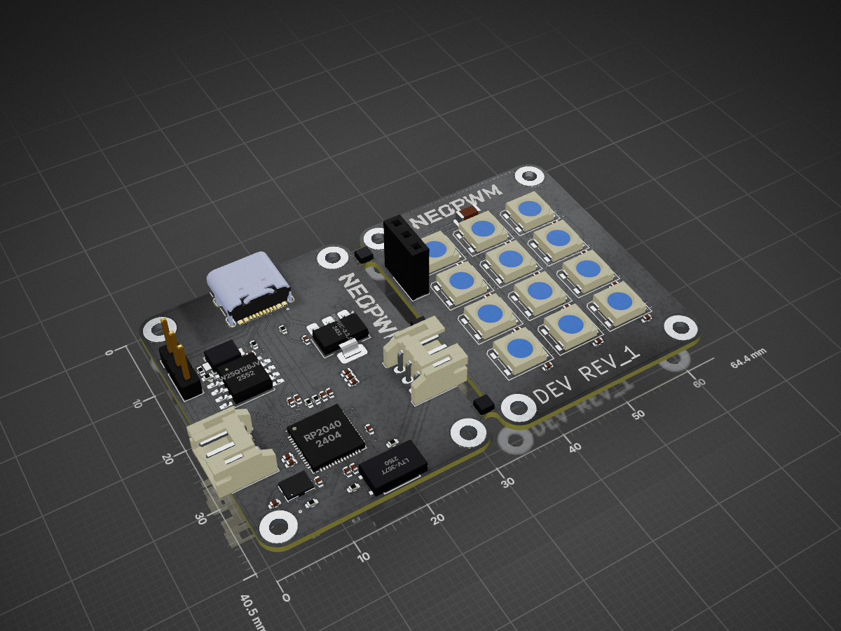
2 layers64.4 × 40.5 mmNeoPWM, the printed circuit board in 3D

The best led controller for FTC

Size
64.4 × 40.5 mm
Copper layers
2
Thickness
1 mm
Parts
72
Nets
73
Pads
272
Tracks, vias
346, 39
Pours
6
Routed
Yes
KiCad
KiCad 9.0 (file 20241229)
Created
17 May 2025
Updated
20 Jun 2025

Overview

NeoPWM is an open-source printed circuit board by PythonAtSea, from the PythonAtSea/NeoPWM repository on GitHub. It is a 2-layer board of 64.4 × 40.5 mm with 72 parts on 73 nets, routed with 346 tracks and 39 vias.

It is built around the RP2040, W25Q128JVSIQ and LTV-357T, with the SK6812, ABM8-272-T3 and TYPE-C-31-M-12 among its other parts. Its parts include 29 capacitors, 12 diodes, 9 resistors, 5 connectors and 4 ICs. It belongs with the RP2040 boards of this library.

Main components

6

README

README.md

NeoPWM

The best led controller for FTC

[!NOTE] This is a Highway project, if you're here from slack (or just want to see the process of development) see JOURNAL.md, for the BOM see BOM.md

[!CAUTION] Curently the PCB has the USB data lines swapped, will fix soon™

What is it?

The NeoPWM is a PWM controlled, USB-C powered, highly configurable SK6812/WS2801 (NeoPixel) controller designed for the FIRST Tech Challenge (FTC). It will have a web based tool to generate configuration files and send over a serial interface. It will have poweron and PWM signal loss states, which allow led patterns to be triggered after a match and during the transition period. It also has a optional intergrated LED panel with 12 SK6812 LEDs, which will have prebuilt patterns.

Why did I make it?

In FTC, there was never a great way to control LEDs. YOu could control a strip of leds over I2C using a I2C to NeoPixel driver, but the I2C ports on the REV Control Hub are slow, which ruins your loop times which causes problems with odometry. You could use the REV Blinkin (no that's not a typo) which is controlled over I2C, but you can't do any configuration and it's powered from the main robot battery. The NeoPWM can be powered from a external USB-C battery and will have a web tool to configure the patterns, and it will have a intergrated LED panel like the CTRE CANdle, but it will be optional, saving costs for teams who just want a LED strip.

NeoPWM in default configuration without LED panel.

image

NeopPWM with intergrated LED panel

image

Both PCBs connected with 2mm mousebites

image

Main schematic

image

RP2040 circuitry schematic

image

BOM

NameLinkPrice
PCBN/A$2.00
PCB AssemblyN/A$31.64
JLC ShippingN/A$52.31
JLC TotalN/A$76.95
JST PH Connectorhttps://www.digikey.com/en/products/detail/jst-sales-america-inc/S3B-PH-K-S/926627$1.31
DuPont connectorhttps://www.digikey.com/en/products/detail/amphenol-cs-fci/68604-403HLF/5206799$1.15
Sk6812 Striphttps://www.digikey.com/en/products/detail/dfrobot/FIT0750/14322609$23.62
DigiKey ShippingN/A$6.99
DigiKey TotalN/A$37.91
M2 Screwshttps://www.aliexpress.com/item/3256806025233809.html$1.34
M2 Standoffshttps://www.aliexpress.com/item/3256804631738035.html$2.46
Aliexpress TotalN/A$3.80

[!CAUTION] This project has not been built physically, so it may or may not work as intended.
Parts

72
QtyValueFootprintReferences
22100nCapacitor_SMD:C_0402_1005MetricC11, C12, C13, C14, C17, C18, C19, C20, C21, C22, C23, C24, C25, C26, C27, C28 +6
12SK6812LED_SMD:LED_SK6812_PLCC4_5.0x5.0mm_P3.2mmD1, D2, D3, D4, D5, D6, D7, D8, D9, D10, D11, D12
8MountingHole_PadMountingHole:MountingHole_2.2mm_M2_PadH1, H2, H3, H4, H5, H6, H7, H8
3VAL**jank:mouse-bite-2mm-slotmouse-bite-2mm-slot, mouse-bite-2mm-slot, mouse-bite-2mm-slot
210uCapacitor_SMD:C_0402_1005MetricC1, C2
215pCapacitor_SMD:C_0402_1005MetricC15, C16
21kResistor_SMD:R_0402_1005MetricR3, R4
21uCapacitor_SMD:C_0402_1005MetricC3, C10
227Resistor_SMD:R_0402_1005MetricR7, R8
25.1kResistor_SMD:R_0402_1005MetricR1, R2
1100uCapacitor_SMD:C_1206_3216MetricC29
110kResistor_SMD:R_0402_1005MetricR9
14.7kResistor_SMD:R_0402_1005MetricR6
1470Resistor_SMD:R_0402_1005MetricR5
1ABM8-272-T3footprints:ABM8-272-T3_ABRX1
1LTV-357TLTV-357T:LTV-357T_LTOU4
1Light Bar Connector (daughter)Connector_PinSocket_2.54mm:PinSocket_1x03_P2.54mm_VerticalJ5
1Light Bar Connector (main)Connector_PinHeader_2.54mm:PinHeader_1x03_P2.54mm_VerticalJ4
1NCP1117-3.3_SOT223Package_TO_SOT_SMD:SOT-223-3_TabPin2U2
1NeoPixel ConnectorConnector_JST:JST_PH_S3B-PH-K_1x03_P2.00mm_HorizontalJ3
1PWM InputConnector_JST:JST_PH_S3B-PH-K_1x03_P2.00mm_HorizontalJ2
1RP2040RP2040_minimal_r2:RP2040-QFN-56U1
1SW_PushTS-1088-AR02016:SW_TS-1088_XNP-LSW1
1TYPE-C-31-M-12usb-c:HRO_TYPE-C-31-M-12J1
1W25Q128JVSPackage_SO:SOIC-8_5.3x5.3mm_P1.27mmU3

Questions

How big is the NeoPWM PCB?

It measures 64.4 × 40.5 mm and has 2 copper layers, 1 mm thick.

What parts does the NeoPWM use?

72 parts, built around the RP2040, W25Q128JVSIQ, LTV-357T and SK6812. The full list of its parts is on this page, with links to each part's symbol and footprint where PCBKit's library has them.

Where can I download the NeoPWM KiCad files?

From the PythonAtSea/NeoPWM repository on GitHub, at the commit this page was made from: the board is Hardware/v0/NeoPWM.kicad_pcb and its schematic Hardware/v0/NeoPWM.kicad_sch. PCBKit opens the board in the browser, with nothing to install.

Can I use the NeoPWM design in my own project?

Its repository states no licence, so its author keeps all rights: ask PythonAtSea before reusing the design.

Similar boards

  • 2 layers149 × 224 mmGDEK, the printed circuit board in 3D

    GDEK

    GilDev/GDEK

    Low-profile, compact, beginner-friendly, assembly-friendly 4×6 with 5-keys thumb cluster ergonomic keyboard with universal keyswitch support, per-key RGB LED, encoder and RP2040 controller. Phew, that’s a lot!

    324 parts3CERN-OHL-S-2.0
  • 4 layers280 × 150 mmUdong, the printed circuit board in 3D

    Udong

    palthedog/Udong

    113 parts1
  • 4 layers40 × 60 mmTrinketcore, the printed circuit board in 3D

    Trinketcore

    alph4345/test

    TrinketCore puts everything a small rechargeable gadget needs on one 40 × 60 mm board, ready to order assembled from PCBWay:

    113 parts
  • 4 layers58 × 70 mmProbelab, the printed circuit board in 3D

    Probelab

    enkhbold470/kicad-projects

    Five KiCad 10 boards (4- and 6-layer): ESP32-S3 industrial gateway, USB-C PD bench supply, RP2040 logic analyzer, FOC motor controller, iCE40 FPGA board.

    88 partsCERN-OHL-S-2.0
  • 2 layers46 × 42.8 mmDaughter board, the printed circuit board in 3D

    Daughter board

    cookiemonsternz/lensboard

    Lens Board is a custom mechanical keyboard, with a modified 1800's layout, more physical input methods (sliders, scrolly wheel, touchscreen) and an inbuilt, physical audio visualizer.

    36 parts
  • 2 layers75 × 75 mmMk9-badge, the printed circuit board in 3D

    Mk9-badge

    hamster/mk9-badge

    dczia's defcon 34 badge

    92 parts
  • 6 layers160 × 100 mmHet68-core, the printed circuit board in 3D

    Het68-core

    fedurca/het68_pcb

    pcb design description

    134 parts
  • 4 layers50 × 70 mmRp569, the printed circuit board in 3D

    Rp569

    kelu124/rp569

    RP569 - PIOs to usb3 ( rp2350 x ch569 )

    146 parts3