2 layers43.9 × 27.7 mm

 pstimpel/emffinder7
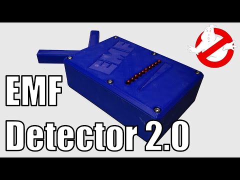
3d Printed arduino based emf detector
Emffinder is an open-source printed circuit board by pstimpel, from the pstimpel/emffinder repository on GitHub. It is a 2-layer board of 74.9 × 92.7 mm with 19 parts on 33 nets, routed with 118 tracks and 3 vias.
Its parts include 11 diodes, 4 connectors and 2 resistors.
License: https://creativecommons.org/licenses/by-nc-sa/4.0/
The result of this project is a 3D printed, arduino nano driven EMF detector. Yes, you could go for hunting ghosts, or you could try to find sources of electro magnetic fields creating noise in your speakers, or killing the functionality of your gadgets.
https://www.prusaprinters.org/prints/21355-emf-finder-detector-20
https://pinshape.com/items/59651-3d-printed-emf-finder-detector-20
https://www.thingiverse.com/thing:4153746
Yes, this project is based on some videos I found. However, I thought I could push it further. This design does only use one resistor to drive all of the LEDs, other designs were using 10 of those, which is kind of a waste. And, I thought it would be cool to be able to change the sensitivity. So I added a switch to do exactly that.
First we need to create the PCB. You can do it yourself which I find is much fun. Or you could send the files to your favorite supplier.

Once you received the board, you have to solder the parts to it. Put the board in front of you, copper side down, two big holes upwards. I suggest you this order, but put the Arduino sketch onto your Arduino before soldering it to the board:
Make sure not to confuse the direction of some parts.

Next, 3D print the items. I was using a .4 nozzle on my Prusa I3 Mk3. I used 0.3 layer hight, 3 shells horizontal and vertical, and 10% cubic infill. No support needed.
Now mount the PCB into the Base, using 3 screws M3x8 cylinder head. Solder 2 100mm wires to the switch, repeat this for the second switch. Mount the switches into their position of the Base.

Cut the more heavy wire into half, and use something small like a small pencil to create your antennas by fiddling the wire around the pencil. Do this twice, and cut 3cm of the isolation if each antenna wire.

Connect it to each other, and mount it into the 3D printed Antenna piece. Now, push it through the big hole at the upper side of the base. Connect it to the left connector of the screw terminal top/middle of the PCB. Use 2 M3x8 cylinder head screw to mount Antenna to Base.
Connect the On/Off switch to the left side, upper screw terminal.
Connect the Range switch to the top right screw terminal.
Connect the battery connector to the left screw terminal, left side, bottom. Ground is the upper connector, voltage is the connector downwards.
Time for a first test. Connect the battery, switch your device on using the upper switch. You see the LEDs flickering? If not, approach something like a TV, or mobile phone. Using the lower switch, you can switch between two ranges of sensitivity.
If all works as expected, put the Top onto the Base, and use 6 M3x8 cylinder head screws to close your device.
Finally, put the battery into its place, and close the battery case useing the Cover, and the M3x8 countersunk screw.

Done!
| Qty | Value | Footprint | References |
|---|---|---|---|
| 10 | L | LED_THT:LED_D5.0mm | D1, D2, D3, D4, D5, D6, D7, D8, D9, D10 |
| 1 | 1N4007 | Diode_THT:D_DO-41_SOD81_P10.16mm_Horizontal | D11 |
| 1 | 3.3 MOhm | Resistor_THT:R_Axial_DIN0204_L3.6mm_D1.6mm_P7.62mm_Horizontal | R2 |
| 1 | 330Ohm | Resistor_THT:R_Axial_DIN0204_L3.6mm_D1.6mm_P7.62mm_Horizontal | R1 |
| 1 | Antenna | TerminalBlock_RND:TerminalBlock_RND_205-00001_1x02_P5.00mm_Horizontal | J3 |
| 1 | ArdNano3 | Module:Arduino_Nano | A1 |
| 1 | Buzzer | Buzzer_Beeper:Buzzer_12x9.5RM7.6 | BZ1 |
| 1 | Power | TerminalBlock_RND:TerminalBlock_RND_205-00001_1x02_P5.00mm_Horizontal | J1 |
| 1 | SwitchPower | TerminalBlock_RND:TerminalBlock_RND_205-00001_1x02_P5.00mm_Horizontal | J2 |
| 1 | SwitchRange | TerminalBlock_RND:TerminalBlock_RND_205-00001_1x02_P5.00mm_Horizontal | J4 |
It measures 74.9 × 92.7 mm and has 2 copper layers, 1.6 mm thick.
19 parts. The full list of its parts is on this page, with links to each part's symbol and footprint where PCBKit's library has them.
From the pstimpel/emffinder repository on GitHub, at the commit this page was made from: the board is pcb/emffinder.kicad_pcb. PCBKit opens the board in the browser, with nothing to install.
Its repository states no licence, so its author keeps all rights: ask pstimpel before reusing the design.

hackclub/OnBoard
💡 Join 1,000 teenagers and make your first PCB with a $100 grant!

polpo/picogus
Emulation of ISA sound cards and CD-ROM on Raspberry Pi Pico (GUS, SB/Adlib, MPU-401, Tandy, CMS, Panasonic CD-ROM) with USB mouse/joystick support


nkitanov/iaq_board
IAQ Board is a DIY (Do-It-Yourself) device for measuring internal air quality


Ardumower/ardumower
Develop an open source robotic lawn mower (HW+SW reference platform)

zmaker/arduino_cookbook
gli sketch del nuovo progetto Arduino Cookbook e dei video di YouTube