
2 layers57 × 55.2 mm
LogicAnalyzer
gusmanb/logicanalyzer
24 channel, 100Msps logic analyzer hardware and software
10 parts5.1kGPL-3.0

 pski/fd50to3414
Adapt 34 Pin Floppy Drives to 50 Pin Controllers
Fd50to34 is an open-source printed circuit board by pski, from the pski/fd50to34 repository on GitHub. It is a 2-layer board of 35.6 × 83.8 mm with 10 parts on 30 nets, routed with 202 tracks and 28 vias.
It is built around the PBC03SBAN and PBC02SBAN. Its parts include 4 resistors and 2 connectors.
This board is a cable adapter to allow 3.5" or 5.25" floppy disk drives to be connected to computer systems with floppy disk controllers that are designed for use with 8" floppy disk drives. It is inspired by instructions by Frank Durda IV for connecting 5.25" floppy disk drives to Radio Shack/Tandy model II, 12, 16 and 6000 computers, as found at this URL:
http://nemesis.lonestar.org/computers/tandy/hardware/model16_6000/floppyfix.html
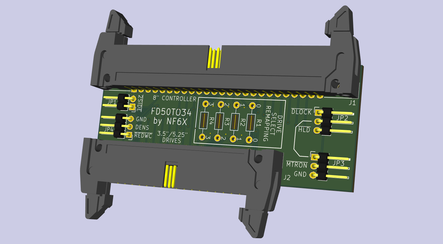
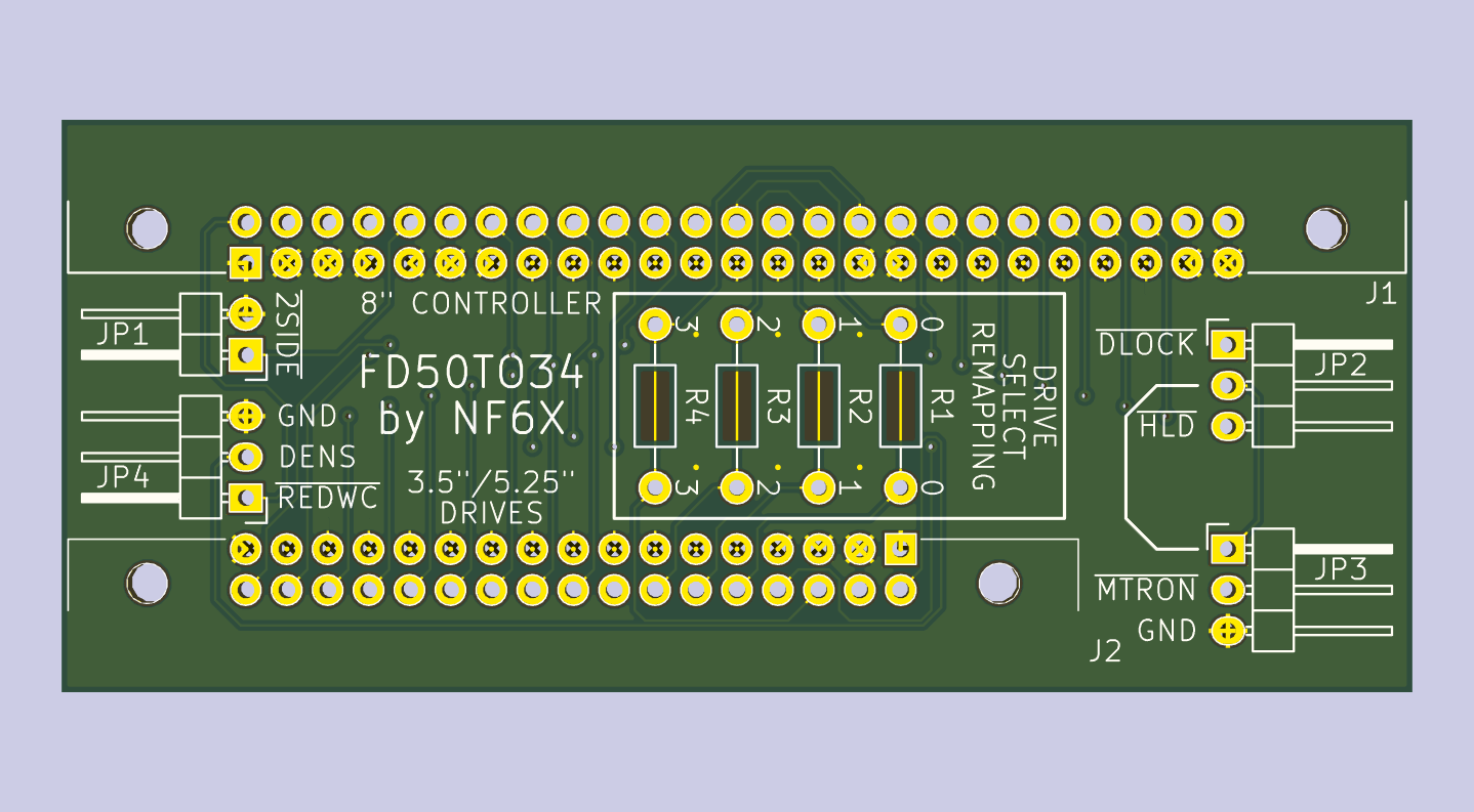
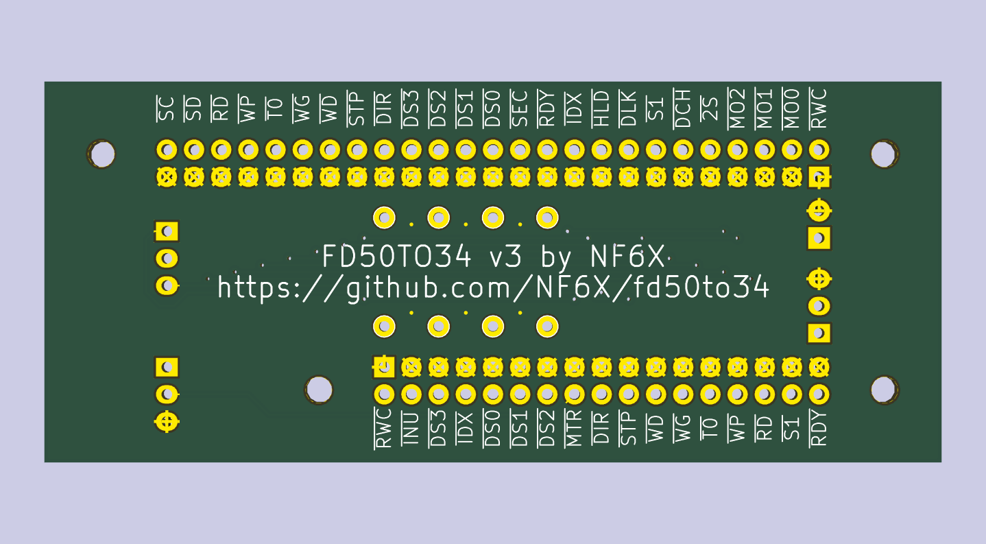
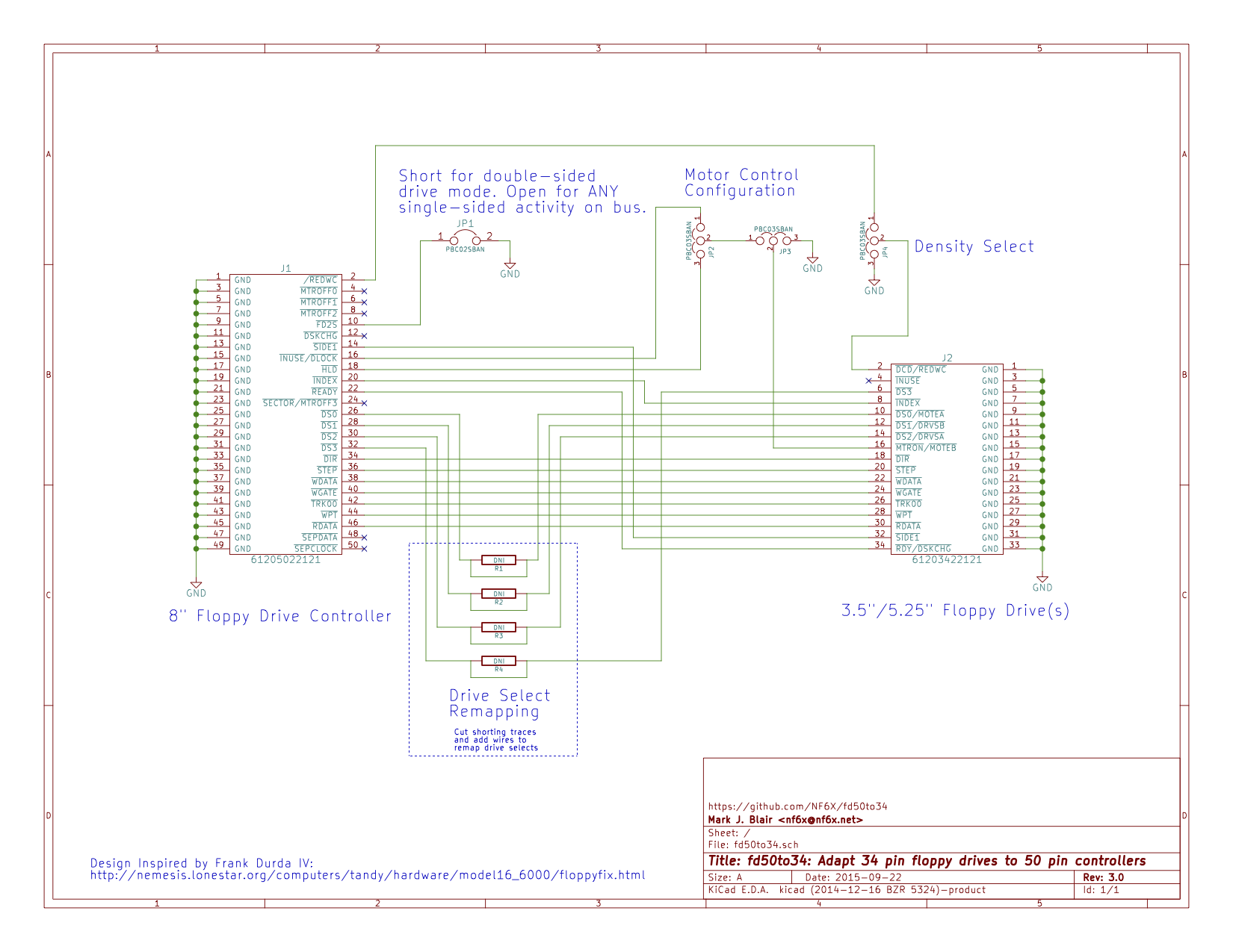
Install a jumper at JP1 to enable double-sided disk support. If any single-sided disks will be used, remove this jumper while accessing them, since installing this jumper makes the controller think that all drives are reporting double-sided media.
If desired, connect a remote SPST switch to this jumper, and close it to enable double-sided media.
Frank recommends strapping the motor control line to ground to force the drive motors on, since 8" drive motor control works differently than 3.5" and 5.25" drive interfaces expect. To get this behavior, install a jumper between pins 2 and 3 of JP3 (labeled MTRON and GND on the PCB). JP2 is ignored in this configuration.
Some drives can be configured to qualify their motor controls with the drive select signals. With these drives, you may wish to experiment with different motor control schemes. To enable these schemes, first move the jumper on JP3 to pins 1 and 2. Then, install a jumper on JP2 to connect the motor control signal to either the head load signal or the door lock signal.
When connecting a Lotharek floppy drive emulator to a TRS-80 Model II/12/16/6000, the door lock signal seems to work well for drive motor control. For this configuration, install a jumper between pins 1 and 2 of JP2, and another jumper between pins 1 and 2 of JP3.
Some floppy drives use J2 pin 2 to select different density modes. On compatible 3.5" drives, pulling this pin down will select a 360 RPM mode which may work well on systems expecting 8" floppy drives. To do this, install a jumper between pins 2 and 3 of JP4. Install no jumper on JP4 for default behavior.
Installing a jumper between pins 1 and 2 connects the reduced write current signal on the 8" interface to J2 pin 2, which is also used to select reduced write current on some 5.25" drives. This option is experimental.
If you need to remap the drive select signals, first cut the exposed traces on the top side of the board which short out resistors R1 through R4 (which are not normally installed). Then, solder wires between the pads of R1-R4 to map the drive select signals as needed.
| Refs | Manufacturer | Part Number | Comments |
|---|---|---|---|
| J1 | Wurth | 61205022121 | |
| J2 | Wurth | 61203422121 | |
| JP1-JP4 | Sullins | PBC36SBAN | Cut to length |
| Jumpers | Sullins | QPC02SXGN-RC |
This board was designed in Kicad 2014-12-16 BZR 5324 on a Mac. Design rules are 6 mil line, 6 mil trace, 13 mil via hole. It is suitable for fabrication at OSH Park.
It measures 35.6 × 83.8 mm and has 2 copper layers, 1.6 mm thick.
10 parts, built around the PBC03SBAN and PBC02SBAN. The full list of its parts is on this page, with links to each part's symbol and footprint where PCBKit's library has them.
From the pski/fd50to34 repository on GitHub, at the commit this page was made from: the board is fd50to34.kicad_pcb. PCBKit opens the board in the browser, with nothing to install.
Its repository states no licence, so its author keeps all rights: ask pski before reusing the design.
gusmanb/logicanalyzer
24 channel, 100Msps logic analyzer hardware and software

byrantech/laptop
anyon_e, a highly integrated, high end, open source laptop. Attempt the impossible.

joeycastillo/Sensor-Watch
A board replacement for the classic Casio F-91W wristwatch


OLIMEX/OLINUXINO
OLINUXINO is Open Source / Open Hardware, low cost from EUR 24 Linux Industrial grade Single Board Computer capable to operate -25+85C

rusefi/rusefi
rusefi - GPL internal combustion engine control unit

VoronDesign/Voron-Hardware
Cool Hardware designed by the Voron Design group

hoglet67/RGBtoHDMI
Bare-metal Raspberry Pi project that provides pixel-perfect sampling of Retro Computer RGB/YUV video and conversion to HDMI